
Chamber quality control and acceptance criteria - PowerPoint PPT Presentation
Title:
Chamber quality control and acceptance criteria
Description:
We suggest to adopt 4 ... Low dark current (and % of pads in hospital) ACCEPTABLE (average gain ... all bigap currents SLIGHLTY PESSIMISTIC conclusions ... – PowerPoint PPT presentation
Number of Views:61
Avg rating:3.0/5.0
Title: Chamber quality control and acceptance criteria
1
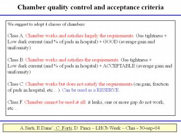
Chamber quality control and acceptance criteria
We suggest to adopt 4 classes of chambers Class
A. Chamber works and satisfies largely the
requirements Gas tightness Low dark current
(and of pads in hospital) GOOD (average gain
and uniformity) Class B. Chamber works and
satisfies the requirements Gas tightness Low
dark current (and of pads in hospital)
ACCEPTABLE (average gain and uniformity) Class
C. Chamber works but does not satisfy the
requirements (on gain, fraction of pads in
hospital, etc). Can be used as a RESERVE. Class
F. Chamber cannot be used at all it leaks, one
or more gap do not work, etc
A.Sarti, E.Dane, C. Forti, D. Pinci LHCb Week
Chia - 30-sep-04
2
Gas tightness
Requirement on gas tightness The acceptance
criterium is -d?P/dt lt 2 mb/h. Corrections for
temperature and external pressure variations have
to be taken into account. ? in LNF we use a
reference chamber
- Chambers measured in LNF55 Leaking 2
- Ch.3 5 mb/hr not recoverable
- Ch.9 2.3 mb/hr probably can be repaired
3
Wire pads in hospital
- Measurement in LNF over 58 chambers produced
- 39 chambers have 0 nA/gap _at_ 2.75-2.85 kV
- 16 with wire pads drawing current (hospitals) to
be recovered - 2 have not been measured still
- 1 have big gas leaks ? have not been measured
Since 3 weeks we are doing a slow conditioning
of the chambers before the source test 7 days
ramping up from 2 kV to 2.8 kV. All 12 chambers
conditioned in this way have no pads in hospital.
We plan to measure with C.R. the effect of wire
pads in hospital on the 4-gap efficiency (we
expect about 99 (4-gap) ? 97 (3-gap) ? 95
(2-gap) ).
- Possible criteria Consider as a RESERVE the
chamber with - the fraction of pads in hospital in the 4-gap is
gt 2 (??) - At present we have 5 chambers with gt 4/192 pads
in hospital, - which will soon undergo the slow conditioning.
4
Dark current
- For what concern dark current, we do not
understand the different behavior - of PNPI and LNF chambers.
- If we have hospitals, there is no way to go up
with HV we see problems already _at_ 2-2.2 kV (with
current limitation of 400 nA). If we have no
hospitals, the displayed current is 0 (up to
2.75-2.85 kV). - In some PNPI chambers there is a dark current
already _at_ 2.5 kV it seems to be a component
almost independent from HV. Why ?
Possible criteria Consider as a RESERVE the
chamber with I(dark) gt 40 nA _at_ 2.8 kV
5
Gain average and uniformity (I)
The goal to have all detector area within the HV
plateau defined by the mimum efficiency and by
the maximum cluster size
M1 the chamber is a bigap the efficiency must
be e gt 99 The bigap cluster size must be lt 1.2
M2-M5 the chamber is a 4-gap the efficiency of
each bigap must be e gt 95 The 4-gap cluster
size must be lt 1.2
From testbeam of LNF chambers, these requirements
define the following 170 V wide regions M1 2720
85 V M2-M5 2620 85 V
6
Gain average and uniformity (II)
The criteria that I suggested before Firenzes
PRR are too complicated.
After measuring 50 chambers in LNF with the
radioactive source, we have lt I(gap) gt235 nA and
lt I(bigap) gt 470 nA. A. For each gap i of a
chamber, the average current I(i) must
satisfy lt I(gap) gt/2 lt I(i) lt lt I(gap) gt2
(equivalent to 105 V range) For each bigap j
of a chamber, the average current I(j) must
satisfy B1. lt I(bigap) gt/1.25 lt I(i) lt lt
I(bigap) gt1.25 (equivalent to 34 V
range) B2. lt I(bigap) gt/1.5 lt I(i) lt lt I(bigap)
gt1.5 (equivalent to 60 V range)
7
Gain average and uniformity (III)
- Requirements on the gain spread
- C1. in both double gaps
- F1.3 (or DV40 V) over at least 95 of the
chamber area. - Flt1.5 (or DVlt60 V) over 100 of the chamber area.
- C2. the chamber fails test C1 but, in both double
gaps - F1.5 (or DV60 V) over at least 95 of the
chamber area. - Flt1.7 (or DVlt80 V) over 100 of the chamber area.
- C3. If the chamber fails test C2 but, in both
double gaps - - F1.7 (or DV80 V) over at least 95 of the
chamber area. - The chamber is accepted (GOOD) if it satisfies
requirements A, B1, C1 - The chamber is accepted as SPARE chamber If it
satisfies the requirements A, (B1 and C2) or (B2
and C1) or (B2 and C2). - The chamber is accepted as a RESERVE if it
satisfies only B2 and C3 - requirements.
8
Old criteria results
- The chamber is accepted (GOOD) if it satisfies
requirements A, B1, C1 - The chamber is accepted as SPARE chamber If it
satisfies the requirements A, (B1 and C2) or (B2
and C1) or (B2 and C2). - The chamber is accepted as a RESERVE if it
satisfies only B2 and C3 - requirements.
Results of the 52 tested chambers (C criteria is
referred to the bigap own average) 37 GOOD 13
SPARE 2 RESERVE
- There are many SPARE because these requirements
are too tight - For each bigap j of a chamber, the average
current I(j) must satisfy - B1. lt I(bigap) gt/1.25 lt I(i) lt lt I(bigap) gt1.25
(equivalent to 34 V range) - C1. in both double gaps
- F1.3 (or DV40 V) over at least 95 of the
chamber area. - Flt1.5 (or DVlt60 V) over 100 of the chamber area.
9
New criteria on gain average and uniformity
Each bigap is classified in A,B,C classes
according to A. lt I(bigap) gt/1.4 lt I(i) lt lt
I(bigap) gt1.4 (equivalent to 50 V range) B.
lt I(bigap) gt/1.7 lt I(i) lt lt I(bigap) gt1.7
(equivalent to 80 V range) C. Requirement B
not satisfied ? DV gt 80 V
The conditions above can be required on 100 of
the bigap area, excluding the pads in hospital
from the calculation, but setting a limit on the
fraction of wire pads in hospital (for ex. lt 2).
- The average current lt I(bigap) gt can be
- the average current of the bigap considered ?
OPTMISTIC conclusions - the average of all bigap currents ? SLIGHLTY
PESSIMISTIC conclusions - the average of all bigap currents, after an
equalization shifting the HV of the bigap
considered by 34 or 0 or 34 Volt ? REALISTIC
conclusions
10
Equalization of the average gap gain
For each gap we find the shift DV required to
align its own average current with the
average current of all the gaps together ltIgt235
nA
HV system with 3 HV HV0 , HV0 D D 34 V from
minimization
HV system with 5 HV HV0 , HV0 D, HV0 2D D
23 V from minimization
11
Effect of equalization
Percentage of bigaps which have 100 of the area
(excluding the hospitals) within a certain range
(50 or 80 V) from the average current of all
bigaps. HV systems with 1,3,5 HV values are
compared.
Without equalization only 94 of the bigaps have
100 of their area in the plateau range ( 80 V)
Without equalization only 75 of the bigaps have
100 of their area in the range 50 V
12
New criteria results and conclusions
For each bigap, we provide the class A 100 of
bigap area in DVlt50 V B 100 of bigap area in
DVlt80 V C not satisfying criteria A and B
Chamber class AA,AB,BAGOOD BBSPARE BC,CB,CCRES
ERVE
- Results of the 52 tested chambers
- Referred to its own average 0 reserve 1 spare
51 good - Without equalization 3 reserve 3 spare 46 good
- With 3 HV values 1 reserve 2 spare 49 good
- Note 5 good chambers have gt2 of pads in
hospital (gt4 pads) and will be remeasured after
slow conditioning
CONCLUSIONS assuming that we reject 1 chamber
broken during GIF test, 1 chamber leaking, 1
RESERVE and 3 (out of 5) with too many hospitals,
we still have 52 M3R3 chambers (48 needed) - this
is the PESSIMISTIC scenario.
13
List of results with new criteria
14
Equalization of the average gap gain
Ch.40 Current in Bigap AB
Shifting the HV by -34 Volts, the average current
gets very close to the average of all bigap
currents 470 nA.
580 nA
463 nA
-34 V
After eq.
Before eq.
15
Plateau width (M2-M5)
From testbeams plateau width170 V for bigaps
150 V for 4-gaps
Lower plateau limits 95 for bigap (2.53 kV) /
99 quadrigap (2.55 kV)
Upper limit cluster size in quadrigap lt 1.2 ? HV
lt2.7 kV (calculated from oct03 results on the
bigaps)
2.62 0.075 kV
99
Testbeam oct. 03 BIGAP
GIF july 04 4-GAP
16
Plateau width (M1)
FROM OCT03 (BIGAP) Upper limit cluster size
1.2 in bigap HV2.82 kV
FROM GIF Lower plateau limit e99 in
double-monogap ? HV2.65 kV
Work point 2.72 kV Plateau width 170 V
GIF july 04 DOUBLE-MONOGAP
Testbeam oct. 03 BIGAP
17
Method for uniformity studies
For each chamber we have
For each gap we have the current in 48x3 cells
The gap uniformity is given by the current range
of 95 of the cells lt I gt/F lt I(95) lt lt I gtF
(where ltIgt is the average current in the
gap) From F we find a voltage range DV where DV
(lnF/ln2)105
18
No-compensation ofbent panel effect
C
Ex. of chamber 31 here the dependences of the
current on the wire pad number are similar in
gaps C and D, so there is no compensation.
D
CD
19
No-compensation of bent panel effect (ch.31)
Even in this bad case, we have that 95 of the
CD area is within 33.8 Volt from the average
current. This is equivalent to the
requirement ltIgt/1.25 lt I(95) lt ltIgt1.25
20
Compensation of 2 adj. Gaps (ch.7)
A
B
AB
21
Uniformity inside each gap
Several panels are bent at the center. This
effect cannot be recovered during
chamber assembly.
However, if the bent panel is a layer 2 or 4
(pad-pad panel) in our R3 chambers, the bigap
uniformity is still good.
Ex. Of chamber 27 the panel between C and D is
bent but the effect is not visible on the bigap
current ? see Pincis talk
The gap uniformity does not profit
of compensation effect it provides a pessimistic
result.
22
Compensation of bent panel effect (ch.27)
95 of the area of the bigap is in a current
range equivalent to DV around the average
current of the bigap lt I gt.
Even with the bent panel the voltage range of
CD is very small DV 15.8 V
23
Equalization of the average gap gain
Without equalization all gaps at same HV
This is the voltage spread DV in each gap to
guarantee that 95 of the gap area is within
DV from the average of all the gap currents
ltIgt215 nA
It is evident that we must set the HV of each gap
to align its gain to the average gain.
24
Effect of equalization
Percentage of BAD bigaps out of a certain DV
range from the average current.
In first column only the effect of intrisic
uniformity of the bigap. In other columns the
range DV is defined around the average current of
all bigaps (i.e. from the HV working point). 1 HV
means that all gaps are set at the same HV (no
equalization)
18 - 2.8 is the effect of the spread of the
average bigap currents (next slide).
The advantage of 5HV with respect to 3HV is poor
(few percent).
25
Effect of equalization spread of the ltIgtof the
bigaps
ltIgt 2 s
No equalization
Band ltIgt/1.25 lt I lt ltIgt1.25
Equalization with 3 HV
Equalization with 5 HV
26
Set of HV values including M1
Working point from testbeams for M1 HV2.72 kV /
M2-M52.62 kV
Set of HV values in a 3 HV equalization system
In this configuration, 6 HV values hospital are
needed
Set of HV values in a 5 HV equalization system
(not needed)
27
Effect of equalization (95 area)
Percentage of bigaps which have 95 of the area
within a certain range (50 or 80 V) from the
average current of all bigaps. HV systems with
1,3,5 HV values hospital are compared.
Without equalization only 95 of the bigaps have
95 of their area in the plateau range ( 80 V)
Recommended
CrystalGraphics Presentations


