
Evaluation results of leadfree solder in power modules - PowerPoint PPT Presentation
1 / 2
Title:
Evaluation results of leadfree solder in power modules
Description:
Evaluation results of lead-free solder in power modules ... reliability to lead-in solder because the fatigue life of ... between soldering temperature(near ... – PowerPoint PPT presentation
Number of Views:58
Avg rating:3.0/5.0
Title: Evaluation results of leadfree solder in power modules
1
Evaluation results of lead-free solder in power
modules
Attachment G
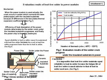
Mechanism When the power module is used
actually, the crack occurs in solder which
connects the base plate(copper) with the
insulated substrate because of differences in the
two plates thermal expansion coefficients. (See
Fig.1)
100
Lead-free solder(Sn-3.0Ag-0.5Cu)
Lead-in solder
75
50
Efficiency of heat dissipation of the power
module deteriorates by the solder crack under the
insulated substrate progresses, and finally the
power chip is thermally destroyed.
Level of solder crack progress (Relative value)
25
0
Equal reliability to lead-in solder cannot be
maintained with lead-free solder because the
crack in lead-free solder progresses faster than
that in lead-in solder. (See Fig.2)
0
300
200
100
Number of thermal cycles (-40?125?)
Fig.2 Evaluation results of the solder crack
progress under the insulated
substrate in power modules
Power Chip
Solder under the Power Chip
Pattern
Ceramic
Conclusion It is impossible that lead-free
solder maintain equal reliability to lead-in
solder because the fatigue life of lead-free
solder is much inferior to that of lead-in
solder used now. (See Fig.2)
Insulated Substrate
Pattern
Solder under the insulated substrate
Solder Crack
Base plate (Copper)
Side of installing Fin
June 25 , 2004
Fig.1 Cross section of the power module
2
Reason why over 85 lead solder cannot be used
Problem in case of 95 lead solder is
used (Liquidus line of 95 lead solder is
314??The solder does not melt completely even if
it is upper 314?. ? Soldering temperature needs
to be near 350?.) ?Deterioration of ceramic in
the insulated substrate Because of difference
between soldering temperature(near 350?) and room
temperature(25?), the micro crack occurs
remarkably in bonded interface between the
ceramic and the conductor pattern, so reliability
becomes deteriorations. ?The curve of the base
plate occurs The base plate(copper) softens
when kept at 350?. (It softens from 8090 to
4050 with vickers hardness in ten minutes.)
When the base plate(copper) softens, the curve of
the base plate occurs.So, the cohesion between
the base plate and the fin deteriorations, and
efficiency of heat dissipation becomes
deteriorations. ?Deterioration of the thermal
cycle reliability In case of using the low
vickers hardness base plate,the curve of base
plate becomes large in thermal cycle test. The
cohesion between the base plate and the fin
becomes deteriorations.Finally, the ceramic in
the insulated substrate is destroyed due to the
curve of the base plate.
Recommended
CrystalGraphics Presentations


