
Idea: Imperceptible UWB - PowerPoint PPT Presentation
1 / 9
Title:
Idea: Imperceptible UWB
Description:
Idea: 'Imperceptible' UWB 'Polite' Co-existence with Licensed Operators: ... Assume Worst-Case Jamming: Infinite 2-D Grid of UWB Aggressors Broadcasting ... – PowerPoint PPT presentation
Number of Views:66
Avg rating:3.0/5.0
Title: Idea: Imperceptible UWB
1
Idea Imperceptible UWB
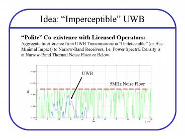
Polite Co-existence with Licensed Operators
Aggregate Interference from UWB Transmissions is
Undetectable (or Has Minimal Impact) to
Narrow-Band Receivers, I.e. Power Spectral
Density is at Narrow-Band Thermal Noise Floor or
Below.
UWB
5MHz Noise Floor
2
UWB Interference vs. Density
What is maximum allowed transmit power?
- Assume Worst-Case Jamming Infinite 2-D Grid of
UWB Aggressors Broadcasting PowerPT Narrowband
Victim at Center - Assume Path Loss Model PR PT(1m/d)n
- Indoor channel measurements suggest n2 (dlt10m),
n3 (dgt10m) - Calculate Aggregate Interference from UWB
Transmitters - At 1m Grid Spacing, PRX 11.5PT
- At 3m Grid Spacing, PRX 0.6PT
- Chose PT s.t. PRX is At or Below Thermal Noise
Floor
3
Link Budget SNR vs. A/D Bits
- Per Pulse SNR
- Pulse is Gaussian Derivative (1ns Edge Rate)
- Channel 3m, 2-wall ray-traced impulse response
- NF 10dB
- Pulse Rep 5MHz
- Pulse PSD Noise Floor
1-bit A/D is Adequate in Noise-Limited Case
4
1-bit Front-End Architecture
Conceptual Half-Circuit of Analog Front-End
fCLK0
fCLK0
fCLK1
fCLK1
- Wideband Real Input
- AGC Not Necessary, Can Fix Gain
- A/D is Sign-Compare
- Very Low Power Consumption
fCLKN
fCLKN
5
1-bit A/D Implications
A/D Circuit Considerations
- Tracking Bandwidth of Switch 1GHz
- Static Sources of Error
- Process Variation
- Circuit/Layout Mismatch
- Dynamic Sources of Error
- Clock Feed-through
- Channel Charge Injection
- Thermal Noise (kT/C)
Create Design Limits
Min. Csample Size, Min. Device Sizes, Min.
Front-end Gain
6
Back-End Digital Correlator
Window Size As Large As Clocking Will Allow (for
Faster Acquisition) Pulse Length Determine From
Channel Delay Spread Matched Filter Coefficient
Quantization Determine From Simulation
7
SNR vs. Interference vs. MF bits
8
Matched Filter quantization error has impact in
high-power interference case. Simulation
suggests 6 to 8 bits.
7
6
5
4
3
2
1
8
Why Need More Bits in MF?
If the Pulse Amplitude is Larger than the
Interferer, a Simple Sign-Compare is Adequate
However, as Inteference Power Increases, the
Quantization Error in the Matched Filter
Coefficients Limits the Ability to Accurately
Recognize the Pulse Shape.
Ex Large Interfering Sinusoid (Narrowband)
Interferer
Full Precision Coefficients
1-bit Coeff. Misestimates Transition
9
MF Coeff. Quantization Limitations
How Well Do We Know the Pulse Shape?
- Received Pulse Shape Changes with
- Antenna Arrival Angle Elevation and Azimuth
- Blocking and Multipath Contributions
- Distance (Near vs. Far Fields)
- Transmitter Variation (I.e. Edge-Rate Changes,
Jitter)
How Well Do We Need to Know the Pulse Shape?
For Acquisition Pulse Shape Has to be Roughly
Similar to What is Expected This Limits the
Practical Usefulness of More Finely Quantized
Coefficients Afterwards We Can Adapt But More
Bits is Only Better if Have Large Interfererers
Practical Limit May Be 6-bits or Less
Recommended
CrystalGraphics Presentations


