
Pulse Width Modulation - PowerPoint PPT Presentation
1 / 19
Title: Pulse Width Modulation
1
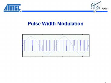
Pulse Width Modulation
2
PWM Features
- General Features
- Four Channels, one 16-bit counter per channel,
- One common clock generator, providing 13
different clocks, - One Modulo n counter providing eleven clocks,
- Two independent linear dividers working on modulo
n counter output, - Channel Programming
- Independent enable/disable commands,
- Independent clock selection,
- Independent period and duty cycle, with double
buffering system, - Programmable selection of the output waveform
polarity, - Programmable center or left aligned output
waveform.
3
View of the external PWM Signals
- 4 Multiplexed Channel outputs with PIOA lines
- Dedicated high current output pad
- Multiplexed to PA0, PA1 and PA2 (respectively for
PWM0, PWM1 and PWM2) allow the user to drive
external circuitry with load current up to 16 mA
(instead of 8 mA for standard pads)
4
PWM into the AT91SAM7S
- PMC has to be programmed 1st for PWM to work
Clock Enabling - Set the PMC_PCER (Peripheral Clock Enable
Register), bit 10 (PID10). - PIO Controller has to be programmed for the pins
to behave as intended - Disable targeted PIO line(s) by using PIO_PDR
(PIO Disable Register) as shown below
- Select between Peripheral A or B, respectively,
in PIO_ASR or PIO_BSR in order to select the PWM
peripheral output channel(s) on the right pad(s).
5
PWM Architecture
- The PWM Peripheral can be split up into two parts
- 1- The PWM Controller which is made of
- Clock Generator gt Clock generation from the
Master Clock (MCK) - Channel Control gt Enable/Disable Channel
- Interrupt Generator
- 2- Channel Modules
- Clock Selector
- Channel Running Mode Manager
- Duty Cycle and frequency Control
- Counter value
- Update register
6
PWMC Clock Generator
PWM_MR (Mode Register)
16
0
23
7
8
11
24
27
PREA
DIVB
PREB
DIVA
1, ½,1/3,..,1/255
1, ½,1/3,..,1/255
CLKA
MCK
CLKB
7
PWMC Channel and Interrupt Management
- At PWMC level, the user can, independently,
enable/disable each channel
PWM_ENA (Enable Register)
PWM_DIS (Disable Register)
0
3
0
3
CHID0
CHID1
CHID2
CHID3
CHID0
CHID1
CHID2
CHID3
PWM_SR (Status Register)
0
3
CHID0
CHID1
CHID2
CHID3
- The user can use the same control panel at
interrupt level plus the dedicated mask register
PWM_IER (Interrupt Enable Register)
PWM_IDR (Interrupt Disable Register)
0
3
0
3
CHID0
CHID1
CHID2
CHID3
CHID0
CHID1
CHID2
CHID3
PWM_ISR (Interrupt Status Register)
PWM_IMR (Interrupt Mask Register)
0
3
0
3
CHID0
CHID1
CHID2
CHID3
CHID0
CHID1
CHID2
CHID3
8
Set up the PWMC in your Application
- Disable the PIO lines and select the right
peripheral between A or B at multiplexing level.
PIO and PWM lines
- For power saving consideration, the PWM s clock
is stoppped at Power Management Controller level
by default.
Enable the PWM Clock
- Set up the targeted clocks which will be used for
the 4 PWM Channels.
Set up the Clock Generator
Channel Enabling
- These tasks can be performed after the complete
channel setting
Interrupt Enabling
9
Set up a PWM Channel
- Per channel
- Channel Mode Register Select the running mode of
the channel - Duty Cycle Register 16-bit value to select the
duty cycle of the signal - Period Register 16-bit value to select the
period of the signal - Counter Register counter value
- Update Register Specific register to modify,
synchronously, the Duty Cycle Register or the
Period Register.
PWM Channel 0,1,2 or 3
PWM Controller
PeriodControl
PWM pad
Comparator
Update Register
Duty CycleControl
CLKA
ClockSelector
CLKB
MCK. down to MCK/1024
Counter
Interrupt
10
First Step Clock Choice
PWM_CMR (Channel Mode Register)
- At Channel level, the Channel Mode Register
allows the user to choose between the 13 sources
from the clock generator
0
3
CLKA
CPRE
CLKB
ChannelsCounter
ClockGenerator
11
What is the best clock source ?
- The PWM duty cycle quantum is the first
criterion - The user has to know his minimum requested
accuracy at duty cycle level. The duty cycle
control is managed through a 16-bit PWM_CDTY
register.
PWM_CDTY (Channel Duty Cycle Register)
N value
0
15
CDTY
- The duty cycle quantum depends on the value
written in Period Register - The M value is the required number of event in
order to complete one PWM channel period (or half
period in center-aligned mode)
PWM_CPRD (Channel Period Register)
M value
0
15
CPRD
The PWM Channel period being equal to M source
period. N will be from 0 up to M value. The
higher M value, the higher the N value can be,
the lower the quantum.
12
Example of different PWM accuracy
- In this first choice, the duty cycle quantum will
be 1/75 of a period
Clock Generator
Clock Generator on(/64)
Channel PeriodRegister 75
CLKA
750 kHz
10 kHz
CLKB
48 MHz
- For the same period, the duty cycle quantum will
be 1/4800 of a period.
Clock Generator
Clock Generator on(1)
Channel PeriodRegister 4800
CLKA
48 MHz
10 kHz
CLKB
48 MHz
13
How to modify a channel Period or a channel Duty
Cycle value ?
- Before to enable the PWM Channel at PWM
Controller level (PWM_ENA Register)The user
will be able to write directly into the PWM_CDTYx
or PWM_CPRDx of this channel, respectively, for a
duty cycle or period change. - As soon as this PWM channel has been enabledIt
is not possible to write into these previous
registers. The user will have to use the Channel
Update Register in order to modify one of the
previous value. - The contain of the Update register is put into
the PWM_CDTY or PWM_CPRD according to the value
of CPD value in PWM_CMR
PWM_CMRx (Channel Mode Register)
0
3
10
CPD
CPRE
PWM_CDTYx
0
PWM_CUPDx
PWM_CUPDx
1
14
Channel Update Register PWM_CUPD
- Why use it
- In running mode, modifying the duty cycle or the
period value can be done only via PWM_CUPD, - The duty cycle or the period modification is
going to be taken synchronously into account at
the end of the period in progress, - How use it
- Before to write in PWM_CUPD, the user will have
to be sure that the last write has been take into
account. In other case, the previous data will be
overlaid by the last one. - Use the bit CPD, in PWM_CMR register, in order to
select a duty cycle or period modification, - Write the data into PWM_CUPD register.
Note It is not possible to modify, in the same
PWM period for one channel, the duty cycle AND
the period values.
15
PWM_CUPD Write method
PWM_ISR (Interrupt Status Register)
- Reading PWM_ISR automatically clears CHIDx flags
0
3
CHID0
CHID1
CHID2
CHID3
0
0
0
0
- Polling or interrupt methods can be used
- A flag rises after an end of channel period
(channel 1 for example)
PWM_ISR (Interrupt Status Register)
0
3
CHID0
CHID1
CHID2
CHID3
0
0
0
1
- Modifying duty cycle or period value in channel 1
can be possible without overlaying risk at
PWM_CUPD level.
16
First Working Mode Left-aligned
PWM_CMR (Channel Mode Register)
When the PWM Counter reach the period value, it
is cleared.
8
9
CALG0Lelt-Aligned Mode
CPOL
PWM_CPRD
PWM_CDTY
0
CPOL 0
CPOL 1
17
Left-aligned Limitation in Multi-Channel use
- The left-aligned working mode does not allow to
avoid overlapped transition in Multi-channel use
In Left-aligned ModeOne event depends on the
duty cycle value and the other depends on the
period value.For the same period, there will be
overlapped event
PWM_CPRD0
PWM_CDTY0
Channel 0Output
The period of both Channels are equal
(PWM_CDTY0 - PWM_CDTY1)
Channel 1Output
PWM_CPRD1
PWM_CDTY1
18
Second Working Mode Center-aligned
PWM_CMR (Channel Mode Register)
8
9
CALG0Lelt-Aligned Mode
CPOL
PWM_CPRD
Count down
Count up
PWM_CDTY
0
CPOL 0
CPOL 1
19
Center-aligned Non-overlapped event Method
- The center-aligned working mode allows to avoid
overlapped transition in Multi-channel use
PWM_CPRD0
PWM_CDTY0
Channel 0Output
(PWM_CDTY0 - PWM_CDTY1)
Channel 1Output
PWM_CPRD1
PWM_CDTY1
Recommended
CrystalGraphics Presentations


