Operational Amplifiers - PowerPoint PPT Presentation
1 / 41
Title: Operational Amplifiers
1
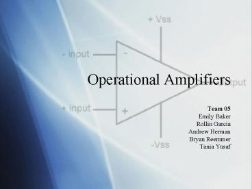
Operational Amplifiers
- Team 05
- Emily Baker
- Rollin Garcia
- Andrew Herman
- Bryan Reemmer
- Tania Yusaf
2
Topics
- History
- Ideal Op-Amps
- Limitations
- Fixes
- Op-Amp Applications
3
Op-Amp
- High Gain Voltage amplifier
- Amplifies difference between 2 inputs
- Positive and negative effect
4
History
- Vacuum Tube Era, 1950s
- 1st used in Analog Computers
- Addition
- Subtraction
- Integration
- Differentiation
- Heavy
- Prone to failure
Analog Computer
K2-W tubes general purpose Op-Amp. 1952
5
History (cont.)
- Now in Integrated Circuits
- 1965- Bob Widlar
- 1st integrated Op Amp bipolar Fairchild µA709
- Lacked short circuit protection
- 2nd 741
- Better performance
- More stable
- Easier to use
6
History (cont.)
- Major Differences
- Internal compensation capacitor
- Extra transistorsshort circuit protection
- New Designs based on
- FET (1970s)
- MOSFET (1980s)
7
Implementation of Op-Amps
- Non-Inverting
- Inverting
8
Implementation of Op-Amps
- Integrator
- Differentiator
9
Implementation of Op-Amps
- Summing
10
Op-Amp Data Sheets
- V Max rail voltage
- V- Min rail voltage
- OUTPUT Vin (resistor ratio 1)
11
The Ideal Op-Amp
12
Voltage Clipping
- Output is AT MOST the supply voltage.
- Output swing further limits the range.
- Parasitic values lead to less than 100
efficiency. - With a 15V supply, one gets a 28V output swing.
13
Slew Rate
- Maximum rate of change of the output voltage for
all possible input signals. - More than 3 distortion if you exceed the slew
rate.
14
Output Swing vs. Frequency
- This graph reflects a combination of both the DC
output swing and the slew rate.
15
Gain-Bandwidth Product
- The GBW for an amplifier is the product of the
open loop gain and its 3 dB bandwidth. - This is about 1 MHz for the LM741.
16
GBP Closed-Loop
- It can be shown that
- Where
- K ideal gain
- ADM open-loop gain
17
GBP Closed-Loop
- It can be shown that
- Where
- K ideal gain
- ADM open-loop gain
Error Multiplier
18
What Does This Mean?
- With a slight approximation of ADM, the error
term reduces to the equation for a pole - Where
19
High-Frequency Response
- Constant gain.
- What happens at higher frequencies?
20
High Frequency Response
- At a frequency fc the Bode plot of the Op-Amp and
the gain of the amplifier meet. - Past fc the gain of the non-inverting amplifier
follows the ADM (open-loop gain) plot.
21
Stability
- The distance from ADM to 1/? is ADM?.
- Intersection point is ADM?1.
- IF ADM?gtgt1 then the gain is K.
- IF ADM?ltlt1then the gain is ADM?K.
- IF ADM?1 then the gain is
22
Stability
- The meaning of this equation is at fc measure the
angle of ADM and place that angle into ADM?. - This equation can cause the instability of the
circuit. - If ADM?180 then the gain is infinity.
23
Stability
- A circuit will be stable if at the frequency
where - ANG(ADM?) 180 MAG(ADM?)lt1
- PHASE MARGIN(PM) 180-ANG(ADM?)
- ROC (SLOPE(1/?)-SLOPE(ADM)) at fc
24
Stability
- For a circuit to be stable
- PMgt45
- 20Db/decltROClt40Db/dec
- For a circuit to be marginally stable
- 0ltPMlt45
- ROC40Db/dec
- For a circuit to be unstable
- PMlt0
- ROCgt40Db/dec
25
Beta Circuit
- Unstable.
- Due to the feedback loop.
- Also due to the 1/? term.
26
Beta Circuit
27
Beta Circuit
- Let C10.1µF and R210K?
- Gain(-R2C2)S where Sj?
- 1/?(1C1 R2S)
- f11/(2?C1R2)159.15Hz
- fc12.616kHz
28
Beta Circuit
- Will not give you 1/?, but ?.
- Take off the op-amp and apply a test voltage at
the output. - Short the input.
29
Beta Circuit
- Gives ?
- Is a flip over the ? axis
- Need to add a zero instead of a pole
- V?? (Voltage divider)
- (1C1 R2S)-1
- Add R1 in series with C1
30
Beta Circuit
- Now there is a zero.
31
Beta Circuit
- Need the zero before fc
- fz1/(2?C1R1)
- Choose fz to be at 9kHz.
- R1177?
- Since R2gtgtR1, f1 stays approximately where it is.
32
Beta Circuit
33
Beta Circuit
34
Beta Circuit
- Check the phase margin.
- Check the ROC.
- The data sheet gives the open loop gain.
35
Op-Amp Applications
- Op-Amps are used in many different situations
such as - Digital-to-Analog Converters (DAC)
- Active Filters
- Precision Rectifiers
- Pre-Amplifiers
- Voltage Clamps
36
Op-Amp Applications (cont.) Digital-to-Analog
Converter (DAC)
- DACs commonly used in MP3 and CD players.
- Op-Amp significance
- Serves as a summer of digital inputs.
- Outputs an analog signal based on gain.
37
Op-Amp Applications (cont.) Active Filters
- Op-Amps frequently used in designs.
- Active Components
- Similar to transistors or vacuum tube
applications. - Op-Amp significance
- Used to shape filters response.
- Used to buffer the filter from other components.
38
Op-Amp Applications (cont.) Precision Rectifiers
- a.k.a Super Diode
- Used in high precision signal processing.
- Converts AC to DC.
- Op-Amp significance
- Aids in controlling the diode
- operation.
- Input positive Diode on
- Input negative Diode off
39
Op-Amp Applications (cont.) Pre-Amplifiers
- Precedes a larger amplifier.
- Used to prepare a signal for greater
amplification. - Used in many audio applications.
- Op-Amp significance
- Input Low-level signal (Microphone)
- Output Line-level signal (MP3, TV)
40
Op-Amp Applications (cont.) Voltage Clamps
- Used to measure ion currents.
- Voltage held at set level.
- Consists of generator with two electrodes.
- Op-Amp significance
- Holds voltage at designated set level.
- Sends error signal.
41
Questions?


