
DIGITAL DESIGN WITH - PowerPoint PPT Presentation
1 / 21
Title:
DIGITAL DESIGN WITH
Description:
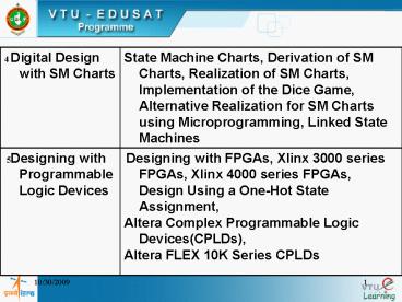
State Machine Charts, Derivation of SM Charts, Realization of SM Charts, ... Moor Type Outputs. 7. 9/24/09. 9. Conditional output list. SM CHARTS ... – PowerPoint PPT presentation
Number of Views:145
Avg rating:3.0/5.0
Title: DIGITAL DESIGN WITH
1
(No Transcript)
2
DIGITAL DESIGN WITH SM CHARTS
K.S.Gurumurthy, M.E, PhD UVCE,Bangalore
1
3
AGENDA
- Motivation
- State Machine Charts
- Example No.1
- Example No.2
- Realisation of SM charts
- Microprogramming
- Linked state machines
- Conclusions
2
4
MOTIVATION
- Digital system design using available ICs
- Not the design of ICs
- System design could become complex
- So think of simpler methods/procedures
- Design should be verified/simulated
Ex SPICE,VHDL
- VHDL is a HDL unlike SPICE
- It is easy to construct VHDL from SM charts
- Hence the emphasis on SM charts
3
5
LOGIC CIRCUITS
Logic Circuits
Sequential (State Machine)
Combinational
Asynchronous
Synchronous
Fundamental mode
Pulse mode
4
6
MOORE TYPE MACHINE
Bistable Memory Devices
Output Combinati onal Logic
Input Combinat- ional Logic
State
External Inputs
Moore Type External Outputs
System Clock
5
7
MEALY TYPE MACHINE
Bistable Memory Devices
Output Combinati onal Logic
Input Combinat- ional Logic
External Inputs
State
Mealy Type External Outputs
System Clock
6
8
MIXED TYPE MACHINE
Moor Type Outputs
Bistable Memory Devices
Output Combinati onal Logic
Input Combinat- ional Logic
External Inputs
State
Mealy Type External Outputs
System Clock
7
9
SM CHARTS
- State machine is used to control a Digital System
- State machine carries out a step-by- step
- procedure or algorithm
- State graphs define state machines
- SM Charts are special type of flow charts to
- describe the behavior of a digital system
/circuit
- SM Charts are used to design control units for
- digital systems
Conditional output list
Ex Binary multiplier, Traffic lights, Dice game
- Easy to construct VHDL descriptions from SM
charts
- These charts will be useful in in the hardware
design
8
10
Components of an SM Chart
Optional State Code
xxx
False Branch
True Branch
Condition
State-name/ Output list
Conditional output list
1
0
b) Decision Box
c) Conditional Output Box
a) State Box
3 Principal components of an SM chart
9
11
Example of an SM Block
One entrance path
S1/Z1Z2
Link path a
X1
SM Block
0
1
1
X3
0
Z3 Z4
Link path b
1
X2
Z5
0
1
n
2
3
n exit paths
10
12
S0 /
S0 /
A
0
1
1
1
ABC
1
C
0
Z1
0
1
B
0
Z1
Equivalent SM Charts for a Combinational Network
11
13
SM Block with feedback
S0/
S0/
X
X
0
0
1
1
Correct
Incorrect
12
14
S0 /Z1
S0 / Z1
1
X3
1
X2
1
X1
X1
0
0
0
Z3
Z4
Z2
Z2
X2
Z3
parallel form
X3
Z4
Serial form
13
15
Example- D Flip-flop
Q
QN
CLK
D
Q
Q
1/1
0 X NC NC
0/0
1/1
S1/1
S0 / 0
0 0 0
0 1 0
0/0
S0 / 0
1 0 1
CLK
D
State Graph
1 1 1
D 1
D Flip-flop
0
Truth Table
1
S1 /1
1
D 1
0
SM CHART
14
16
VHDL CODE FOR D Flip-flop
entity DFF is port (D, CLK in bit Q out
bit QN out bit 1) end DFF Architecture
D_SEQ of DFF is begin process (CLK)
begin if CLK 1 then
Q lt D after 10 ns QN lt not D
after 10 ns end if end
process end D_SEQ
15
17
Conversion of a state graph to an SM chart
1/0
1/0
State Graph
S0/Za
S1/Zb
S2/Zc
0/0
1/Z2
0/0
0/Z1
00
S0 /Za
Link 1
Equivalent SM chart
X
01
S1 / Zb
Link 2
x
11
S2 / Zc
Link3
x
Z1
Z2
16
18
Example - S-R Cross coupled NOR Gate Latch
S-R LATCH
S R Q Q
0 0 0 0
R
a / 0
Q
1 0 0 1
1 0 1 1
0
S.R
0 1 0 0
Q
0 1 1 0
S
1 1 Not allowed
1
0 1 1 1
b / 1
a/0
b/1
S R 0 0 0 1
0 0 1 0
1 0
R
1
State Graph
0
SM chart for S- R Flip-flop
17
19
Example of an SM Chart
S-R Cross coupled NOR Gate Latch
State q
0
a / 0
State Box
0
Exit path for a false condition
Boolean expression representing condition
S.R
1
b/0
Exit path for a true condition
Decision box
R
1
0
18
20
Derivation of SM charts
Method
- Draw the Block diagram of the system to be
controlled
- Define the required input output signals to
the control N/W
- Construct the SM charts from SM Blocks
- Each SM Block contains exactly one state Box
together
with the decision boxes and conditional
output boxes associated with that state
- An SM block has one entrance path and one or
more exit - paths
- Each allowable input combination must lead to a
single - next State
19
21
THANK YOU
Recommended
CrystalGraphics Presentations


