Timing LLRF on RTEMS - PowerPoint PPT Presentation
Title:
Timing LLRF on RTEMS
Description:
EVG200 with up to 2K data buffer transfer. VME-EVR200 ... MIXER. LO. RF. IF. RF Board. 25.5MHz IF. Control Board. Control. EXTERNAL. TRIGGER. 120Hz. EXTERNAL ... – PowerPoint PPT presentation
Number of Views:66
Avg rating:3.0/5.0
Title: Timing LLRF on RTEMS
1
Timing LLRF on RTEMS
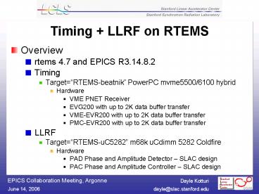
- Overview
- rtems 4.7 and EPICS R3.14.8.2
- Timing
- TargetRTEMS-beatnik PowerPC mvme5500/6100
hybrid - Hardware
- VME PNET Receiver
- EVG200 with up to 2K data buffer transfer
- VME-EVR200 with up to 2K data buffer transfer
- PMC-EVR200 with up to 2K data buffer transfer
- LLRF
- TargetRTEMS-uC5282 m68k uCdimm 5282 Coldfire
- Hardware
- PAD Phase and Amplitude Detector SLAC design
- PAC Phase and Amplitude Controller SLAC design
2
Timing on RTEMS
3
VME PNET Receiver
- Driver support
- Init
- rc devRegisterAddress( "pnet", atVMEA24,
- vmePnetAddr, PNET_DATA_NUM_BYTES,
- (void)pLocalBuf)
- rc devConnectInterruptVME(PNET_IRQ_VECTOR,
pnetISR, 0) - rcdevEnableInterruptLevelVME(PNET_IRQ_LEVEL)
- ISR
- for (ii0 iilt4 ii) / hdr is in first 4
longs, 0-3, and is ignored. - set initial ii val
to 0 if hdr needed - data is in last 4
longs, 4-7, and is of interest / - pnet_messagesnext_message.dataii
in_be32((pLocalBuf-gtdataii)) - / NOW update what current_message is (so that
it will be what's accessed / - current_message next_message
4
VME PNET Receiver data display
5
EVG-EVR transfer timefor 16B data buffer
66.6 µsec
6
EVG-EVR data transfer sequencing
7
EVG-EVR data types
8
LLRF on RTEMS
9
(No Transcript)
10
LLRF Component Types
- Three types of components PAD, VME and PAC.
- 1. PAD the phase and amplitude detector uses
an embedded IOC (uCdimm 5282 Coldfire) - Triggered at 120 Hz, PAD reads 4 channels of
accelerator 119 MHz RF(IQ) from ADCs via TI
FIFOs into EPICS waveform record. - FIFOs are 65536 words long, but operationally we
use fewer (of order 1k), the size depending on
the fill time of the cavity - ADCs are LTC2208 (16 bit, 130 MHz)
- Hardware design and CPLD programming by Ron Akre
(SLAC) - Last summer, no commercial VME ADC board could
match these specifications, so we opted for
in-house solution. - Additional advantage digitizers can be placed
next to the low noise RF components (eliminates
transmission of low noise analog signals outside
the chassis)
11
PAD Block Diagram (2 channels)
12
LLRF Component Types
- 2. VME Feedback Crate uses a mvme6100
- Provides timing trigger to the PAD from EVR200
- Receives averaged IQ (EPICS ai records) from
PAD - Applies phase and amplitude adjustments from
global or local feedback - Sends new IQ (EPICS ao records) to PAC
- Provides timing trigger to PAC where corrected
waveform is sent out (and NEXT PAD values get
read)
13
LLRF Component Types
- 3. PAC the phase and amplitude controller uses
an embedded IOC (uCdimm 5282 Coldfire) - receives the adjusted IQ values (EPICS ai
records) and computes the waveform to be sent out
on next 120 Hz trigger - drives an IQ modulator
- used for control of the LLRF to the solid state
sub-booster - hardware design and FPGA programming by Jeff
Olsen (SLAC)
14
PAC Block Diagram
15
LLRF Component Instances
16
LLRF Component Instances
17
PAD driver details
- Driver support
- init sets up dacq task
- ISR
- / Announce that data is available for read /
- epicsEventSignal(waitForData)
- clear the interrupt
- Dacq task
- waitStatus epicsEventWait(waitForData)
- Device support
- Database records
18
PAD EDM GUIUse this panel to change the
size of and offset to the sample to be averaged.
19
PAC details
- Driver support update FPGA calculation
- Device support
- init waveform record bptr is freed and set to
mem-mapped FPGA space - write waveform is recalculated and result
stored in FPGA - Database records
- in ops, new adjustment FLNKs to waveform
- in cal, new gain or offset FLNKs to waveform
20
PAC edm control
- There are 2 EDM screens
- for startup and calibration
- at startup the amplitude of the calibration
waveform can be modified, as well as number of
points in wf - in calibration, the gain and offset of IQ can
be modified - for operation
- IQ can be adjusted (scalar applied to WFi
gain before offset is added)
21
RTEMS lessons learned


