
Digital Electronics EEE3017W - PowerPoint PPT Presentation
1 / 21
Title:
Digital Electronics EEE3017W
Description:
ATD Interrupt Enabled. Analogue Input Channel Select. ATD Continuous Conversion. 8 ... Taken from Analog Devices MT-021. 15. Digital Electronics EEE3017W. R. ... – PowerPoint PPT presentation
Number of Views:81
Avg rating:3.0/5.0
Title: Digital Electronics EEE3017W
1
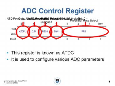
ADC Control Register
- This register is known as ATDC
- It is used to configure various ADC parameters
2
ADC Data Format
- The highest 8-bit 2s complement number that we
can represent is 7F and the most negative is 80
3
ADC Timing
- The PRS bits set the clock prescaler
- This needs to be set to ensure optimal clock
frequency into the ADC - For the ADC to convert as fast as possible it
needs to receive a 2MHz clock - There are many different usable processor speeds
- To ensure that the clocks speeds match, the ADC
contains a clock divider which ensures that the
ADC receives the correct clock frequency
4
Example
- The monitor in our board initializes the clock
frequency to 18.874368 MHz. This must be divided
down to 2MHz to be feed into the ADC. What PRS
value is needed?
5
Solution
6
ADC Pin Enable Register
- As the ADC shares pins with ports
- We need a way to disable port pins and enable
analogue inputs - This is done by setting the bits in this register
7
ADC Status and Control Register
- There is only 1 ADC onboard the GT16
- This means that we need to specifically select
which input will be converted - This register is used to control ADC interrupts
and which input is to be converted
8
Types of ADC
- There are a large number of different types of
ADC. - We will consider some of the more common types
- Ramp Convertors
- Successive Approximation Convertors
- Dual Slope Integration Convertors
- Flash Convertors
- Sigma Delta Convertors
9
Speed vs. Resolution
10
Ramp Convertors
- Very crude ADC
- Consists of a counter which is feed into a DAC
- The counter starts at zero and counts up until
the output of the DAC exceeds the input voltage - The counter code is then taken as the converted
output - Very slow
- Conversion time not constant
- Not very popular
11
Flash Convertors
- Speed
- Very fast (up to GHz)
- Resolution
- 6 to 12-bits
- Cost
- Expensive
- Power Consumption
- High power consumption due to large number of
comparators - Uses
- Building block in other ADCs
- High performance applications
- High speed oscilloscopes
- RF Test Equipment
Taken from www.n-denkei.com
12
Flash Convertors
- Uses a resistor network and comparators to
determine output code - n resistors for an n-bit ADC, divide Vref into
n-1 different voltage levels - Vin is then compared to the Vref
- The output of the comparators is put into a
priority encoder
13
Successive Approximation Convertors
- Speed
- Fairly fast
- Resolution
- 8 to 18-bits
- Cost
- Low Cost
- Uses
- PC DAQ Cards
- Onboard ADCs in Microcontrollers
- ADCs in low cost equipment
14
Successive Approximation Convertors
Taken from Analog Devices MT-021
- Uses a binary search system to find output code
- If we have a 3-bit convertor with an input
voltage which corresponds to an output between
the values of 101 and 110 - The convertor makes the following approximations
- 100 (too low)
- 110 (too high)
- 101 is the final result
15
Dual Slope Integration Convertors
- Speed
- Fairly slow
- Resolution
- Up to 24-bits
- Cost
- Depends on resolution
- Uses
- Popular in DMMs
Taken from Analog Devices MT-027
16
Dual Slope Integration Convertors
- Integrate the input voltage for a known period of
time - Usually by charging a capacitor
- This capacitor is then discharged by integrating
a known negative voltage - The time taken for the capacitor to fully
discharge is measured with a counter - The output of the counter is then the convertors
output
Taken from Analog Devices MT-027
17
Sigma Delta Convertors
- These are quite complicated devices
- Use a delta sigma DAC in a feedback loop
- Typically slower than Flash but offer good
resolution at a good price - Often used in PC Sound Cards
Taken from Analog Devices MT-023
18
ADC Example 1
- This is an example of how to use the ADC in 8-bit
continuous mode - The port is sampled and the result is put on Port
As LEDs
19
ADC Example 1
- XDEF _Startup
- INCLUDE 'derivative.inc
- org ROM1Start
- _Startup
- LDHX 047F Initialize the stack
pointer - TXS
- LDA 53
- STA SOPT Disable the watchdog timer
- MOV FF, PTADD Make PTA an output
- MOV FF, PTAD LED's are off for a logic high
- MOV A4, ATD1C
- MOV 01, ATD1PE Set the PTB0/AD1P0 pin as an
ADC input, rest of the port is IO - MOV 20, ATD1SC Start the converter running in
continuous mode, no - interrupts
- mainLoop
- LDA ATD1RH
- COMA Invert all the bits of the result
because LED's are active
low
20
ADC Example 2
- This is an example of how to use the ADC in 8-bit
interrupting, 1 shot mode - The ADC interrupt initiates the next conversion
- The port is sampled and the result is put on Port
As LEDs
21
ADC Example 2
- XDEF _Startup
- INCLUDE 'derivative.inc
- org ROM1Start
- _Startup
- LDHX 047F Initialize the stack
pointer - TXS
- LDA 53
- STA SOPT Disable the watchdog timer
- MOV FF, PTADD Make PTA an output
- MOV FF, PTAD LED's are off for a logic high
- MOV A4,ATD1C
- MOV 01,ATD1PE The PTB0/AD1P0 pin is an ADC
input - MOV 40,ATD1SC Start the converter in 1 shot
mode, with interrupts - CLI Globally enable interrupts
- mainLoop NOP
- BRA mainLoop
- ADC_IRQ
- LDA ATD1RH