
Lenzs Law - PowerPoint PPT Presentation
1 / 23
Title:
Lenzs Law
Description:
On an electric guitar, the vibrations of the metal strings are sense by electric ... Therefore,the inductance per unit length for a long solenoid near the center is ... – PowerPoint PPT presentation
Number of Views:274
Avg rating:3.0/5.0
Title: Lenzs Law
1
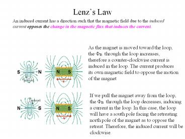
Lenzs Law
An induced current has a direction such that the
magnetic field due to the induced current opposes
the change in the magnetic flux that induces the
current.
As the magnet is moved toward the loop, the ?B
through the loop increases, therefore a
counter-clockwise current is induced in the loop.
The current produces its own magnetic field to
oppose the motion of the magnet
If we pull the magnet away from the loop, the ?B
through the loop decreases, inducing a current in
the loop. In this case, the loop will have a
south pole facing the retreating north pole of
the magnet as to oppose the retreat. Therefore,
the induced current will be clockwise.
2
Lenzs Law
Stratocaster
On an electric guitar, the vibrations of the
metal strings are sense by electric pickups that
send signals to an amplifier. The basic
construction of the pickup are wires coiled
around magnet. The magnetic field from the magnet
produces a north and south pole in the section of
the guitar string just above the magnet. When the
string is struck by a pic and made to vibrate,
its motion relative to the coil changes the flux
of its magnetic field through the coil, inducing
a current in the coil. The induced current
changes direction at the same vibration frequency
of the string.
3
Energy Transfer
Whether you move the magnet toward or away from
the loop, a force resist the motion, requiring
your applied force to do positive work. At the
same time, thermal energy is produced in the loop
due to the loops resistance to the induced
current. The faster the motion, the more rapid
the applied force does work and the greater the
rate of production of thermal energy in the loop.
4
Energy Transfer
x into the page
This figure shows another situation involving
induced current. A rectangular loop of width L
has one end in a uniform external magnetic field
perpendicular to the plane of the loop. The
dashed lines are the limits of the magnetic
field. When the loop is pulled to the right at a
constant velocity, the magnetic flux through loop
changes with time and an current is induced in
the loop.
The situation in the above figure is no different
than that in the figure to the left. In each case
the flux in the loop is changing and an induced
current is produced.
5
Energy Transfer
To pull the loop at a constant velocity, a force
must be applied to loop since an equal and
opposite magnetic force opposes the motion. The
rate of work is applied is
P Fv
where F is the magnetic force opposing the
motion. We want P in terms of magnetic field
strength, the loop resistance and dimensions.
The magnetic flux when x is the length of loop
inside the field is
As x decreases, the flux decreases resulting in
an induced emf in the loop
6
Energy Transfer
Using Faradays Law, we can write the EMF as
where dx/dt v, the speed which the loop is moved
The induced current can be derived from Ohms Law
assuming the loop has a resistance R
Since the 3 segments of the loop in the top
figure carry this current through the field,
magnetic forces are applied. Recalling the force
equation of a wire carrying a current in a
magnetic field.
The forces acting on the loop are marked as F1,
F2 and F3. Note the forces F2 and F3 are equal
in magnitude and cancel. This leaves only F1
which opposes the motion to remove the loop.
Note that the angle between L and B is 900
therefore we can write
7
Energy Transfer
The magnetic force on the loop with current i is
F iLB
Substituting for the induced current
The force required to move loop out of field
region at a constant velocity v. Using this
relationship, we can now obtain the rate of doing
work as we pull the loop.
We now determine the thermal energy in loop.
Recall the equation for thermal energy
dissipated through a resistance.
Substituting for i
which is exactly equal to the rate of doing work
moving the loop
8
Induced Electric Fields
We know that a changing magnetic flux produces an
induced electric current in a conducting loop
the changing magnetic flux creates an electric
field which drives electric charges around the
conducting loop.
Does a changing magnetic flux create an electric
field in empty space, even when no charges are
present ??
Yes !! ?
The fundamental electromagnetic induction effect
is that A changing magnetic flux generates an
electric field
The observed induced EMF and current in
conductors are basically artifacts of the induce
electric field.
As long as the magnetic flux is increasing in
time, the electric field as represented by the
circular field lines as shown in the right
figure, will be present.
9
Induced Electric Fields
Consider a charged particle q0 moving around the
circular path as shown in the figure to the right
The work W done on it in one revolution by the
induced electric field is q0 , where
is the induced EMF, that is, the work done per
unit charge in moving the charge around the path.
The work is
W
where q0 E is the magnitude of the force acting
on the charged particle and 2?r is the distance
over the path . Since EMF is related to work
by We find that
More generally, we can re-write the above work
equation to give the work done on a particle
moving along any closed path.
Substituting for W for q0 , we have
10
Induced Electric Fields
Substituting for EMF
We can now write Faradays Induction Law in a
more fundamental way
It simply says that a changing magnetic field
induces an electric field
In this form, this equation can be applied to any
closed path that can be drawn in a changing
magnetic field
Does the left side of this equation seem odd for
some reason ??
11
Induced Electric Fields
Induced electric fields are produced not by
static charges, but by a changing magnetic flux.
Although electric fields produced either way
exert forces on charged particles, there is an
important difference between them. One obvious
difference between them is that the field lines
of induced electric fields form closed
loops. Field lines produced by static charges
never do so, but must start on positive charges
and end on negative charges. Moreover, the field
originating from electric charges is a
conservative field meaning if an electric charge
is transported around a closed loop, there is no
net work done on the charge, that is,
This basically means that induced electric fields
are non-conservative.
12
Induced Electric Fields
This basically means that induced electric fields
are non-conservative.
Consider what happens to charged particle that
makes a single journey around the circular path
in the figure to the right. When it returns to
the starting point, it has gain potential (a
EMF). This means the same point could have
different values of potential. We must conclude
that potential has no meaning inside induced
electric fields. However, if a path starts at
some point outside an induced electric field
region, enters the region and then ends at some
point outside this region, an unique potential
value can be assigned to this particular path.
13
Inductors and Inductance
We recall that a capacitor can be used to
produced a desired electric field and the
parallel-plate arrangement was used as a basic
type of capacitor. In a similar fashion, an
inductor ( symbol ) can be used to
produced a desired magnetic field and the we will
consider a long solenoid as our basic type of
inductor
If we send a current i in the windings (or turns)
of an inductor (a solenoid), the current produces
a magnetic flux ? through the central region.
The inductance of the inductor is then
where N is the number of turns. The windings of
the inductor are said to be linked by the shared
flux and the product N? is called magnetic flux
linkage. The inductance is a measure of flux
linkage produce by the inductor per unit current
i.
14
Inductors and Inductance
The SI unit of magnetic flux is the tesla square
meter, the SI unit of inductance is the tesla
square meter per ampere (T m2/A). This unit of
inductance is call the Henry.
Now, lets consider a long solenoid of
cross-section A. What is the inductance per unit
length near its middle ??
1st we must calculate the flux linkage N? set up
by the current in the solenoid. Consider a length
l near the middle of the solenoid. The flux
linkage for this section is
N? (nl)(BA)
where n is the number of turns per unit length
and B is the magnetic field within the solenoid
Recall the relationship magnetic field and
current in a solenoid is given by
B ?0 i n
15
Inductors and Inductance
So we make the following substitutions
N? (nl)(BA)
B ?0 i n
into the definition of an inductance
and we then obtain the relationship
Therefore,the inductance per unit length for a
long solenoid near the center is
The inductance like capacitance only depends on
the geometry
Note the n2, the B field and flux linkage both
explicitly depend the winding density
16
Self Inductance
If two coils or inductors are near each other, a
current in the first inductor produces a magnetic
flux through the second inductor. If we changed
this flux by changing current, an induced EMF
appears in the second inductor. Since this
change of current changes the flux within the
first inductor, an induced EMF also appears in
the first inductor as well.
An induced EMF appears in any coil or inductor in
which the current is changing.
This process is called self-induction, and the
EMF that appears is called self-induced EMF. This
process obeys Faradays Law of induction just as
other induced EMFs do.
If the current in a inductor is changed by
varying the contacted position on a variable
resistor, a self-induced emf will appear on the
coil while the current is changing.
17
Self Inductance
Recalling the definition for an inductor slightly
rearranged
Faradays Law is
Combining these two equations we have
The direction of the is found from Lenzs
Law. The self-induced emf acts to oppose the
change in the current.
The above circuit diagrams illustrate that the
change in the current is the change that the self
induction opposes.
We can define a self-induced potential difference
VL across the inductor. If the inductor is ideal
(zero resistance), the magnitude of VL is equal
to the self-induced emf.
18
RL circuits
The circuit diagram to the left shows a simple RL
circuit. When the switch S is closed on a, the
current in the resistor starts to rise. If the
inductor were not in the circuit, the current
would rapidly rise to a steady value of
. The inductor, however, produces an emf
opposing the rise of the current meaning that it
opposes the battery EMF in polarity. Therefore,
the current in the resistor responds to the
difference between the two EMFs, a constant one
(battery) and a variable one (inductor). As time
goes on, the rate at which the current increases
becomes less rapid and the voltage across the
inductor becomes smaller. The current in the
circuit gradually approaches after a long
period.
19
RL circuits
In this circuit, the inductor acts to oppose
changes in the current through it. A long time
later, it acts like an ordinary connecting wire.
With the switch S thrown to point a, the left
circuit is equivalent to circuit diagram above.
If we apply the loop rule starting at x in this
figure and move clockwise around the loop in the
same direction of the current. The potential
change across R is iR For increasing current,
the potential change across the inductor
clockwise is Ldi/dt. We encounter a rise in
potential of across the battery.
Therefore, the loop rule gives us
20
RL circuits
Loop equation
This differential equation is very similar to
the charging RC equation. Using the result
obtained from the RC equation, we find the
solution to the above equation is
Defining the time constant as
We can rewrite the solution as
which has very similar characteristics to the
charging RC circuit
21
RL circuits
Reversing the switch to point b, removes the
battery from the circuit and the current through
the resistor begins to decrease. However, it
cannot drop immediately to zero but must decay to
zero over time.
Without the battery, the loop rule equation now
becomes
The solution to this equation is
This function is almost the identical form of the
discharging capacitor solution.
22
Energy Stored in a Magnetic Field
To derive a quantitative expression for the
energy stored in a magnetic field consider the RL
circuit previously discussed. The voltage
equation is re-stated
If we multiple both sides by i, we obtained the
rate at which the battery delivers energy to the
circuit.
Rate at which energy appears as thermal energy
The rate dUB/dt at which energy is stored in the
magnetic field
23
Energy Stored in a Magnetic Field
So we can write the rate of energy stored in the
magnetic field on the inductor as
The dt cancels out and we are left with
Integrating yields
which represents the total energy stored by an
inductor
Recommended
CrystalGraphics Presentations


