
R - PowerPoint PPT Presentation
1 / 77
Title: R
1
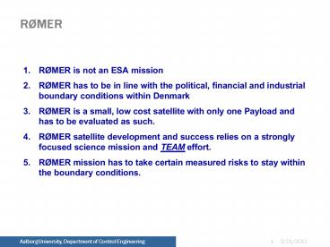
RØMER
2
Political Boundaries
3
Industrial Boundaries
4
Financial Boundaries
5
Ansøgt beløb detailed design fasen
6
Totalt budget RØMER
7
Saml. Ørsted
8
AAU budget
9
AAU budget 2
10
AAU budget - 3
11
Participants
- Science
- Institute of Physics and Astronomy, Aarhus
University - Danish Space Research Institute, Copenhagen
- Copenhagen University
- Technology
- Institute of Electronic Systems, Aalborg
University - Ørsted.DTU, Technical University of Denmark,
Lyngby - Industry
- TERMA A/S, Lystrup
- Alcatel Space Denmark, Ballerup
- Copenhagen Optical Company, Copenhagen
- Patria Finavitec, Tampere, Finland
- Auspace, Canberra, Australia
- Prime Optics, Eumundi, Australia
12
Organization - Organization Chart
13
Milestones
- April 1999 Kick-off of Feasibility Study of Rømer
- May 2000 Funding for System Definition Phase
approved - May 2000 Kick-off of System Definition Phase
(SDP) - Oct. 2000 Mid-Term Review
- Nov. 2000 Decision to eliminate the Ballerina PL
and re-focus mission - Nov. 2000 Decision to design Rømer as a
single-string mission - April 2001 System Definition Review
- May 2001 Complete Report and Documentation for
SDP - June 2001 Start of Detailed Design Phase
- Dec. 2001 Preliminary Design Review
- Dec. 2002 Satellite Critical Design Review
- May 2003 Satellite Integration and Test Review
- May 2004 Launch (tentatively)
14
Rømer Overall Schedule
15
Rømer Overall Schedule 2
16
RØMER SCIENCE OBJECTIVES
- Study the structure, evolution and internal
dynamics of a sample of stars showing
stochastically excited, solar-like oscillations. - This will substantially extend the very
successful helioseismic studies of the solar
interior.
17
Corresponding Observations (SOHO)
- Note
- Extremely small amplitudes, of order parts per
million (ppm). - Blue amplitude much larger than red amplitude.
Hence also signal in (blue)/(red) ratio, to be
observed by MONS. - Background is entirely due to solar granulation.
18
Main MONS Observational Requirements
- Photometric precision. Need detection limit below
1 ppm. - The instrumental noise must match, but be below,
the intrinsic stellar granulation noise. - Requirement on precision demands strong
defocusing. - Temporal coverage. Each primary target must be
observed almost continuously for at least one
month. - Sky coverage. Primary targets are distributed
over the whole sky. - Hence choose orbit giving access to entire sky
during the mission. - Mission duration. At least two years (baseline),
to allow study of sufficient number of stars. - Exclusion of variable neighbours. Include MONS
Field Monitor to detect and correct for faint
variable stars within telescope field of view.
19
RØMER Science Payload Characteristics
- The primary science instruments include
- MONS Telescope having a 32 cm aperture, equipped
with a high-precision photometric CCD detector
for measuring oscillations of stellar intensity
and color - MONS Field Monitor for examining the field of
view of the MONS Telescope for faint variable
stars - The secondary science instruments
- Forward- and aft-looking Star Trackers of the
Attitude Control Subsystem, to be used for
studying variable stars - The MONS Field Monitor
20
Ground Segment Architecture
- One or more Ground Stations
- A Control Center which shall have total control
of the mission and shall provide data processing,
storage and display - A Science Data Center which shall prepare the
specified user data products and disseminate them
to the involved research institutes and
organizations
21
Orbit Requirements
- Maximize time outside the trapped proton
radiation belts - Allow momentum unloading using only magnetorquers
- The operational orbit shall be delivered by the
upper stage of the launch vehicle. - Visibility from a ground station in Denmark
- Frequent launch opportunities to the proposed
orbit (?1 per year)
22
RØMER in Molniya Orbit
- Largest separation from Earth (Apogee) 40000 km
- Smallest separation from Earth (Perigee) 600 km
- Angle between orbit and Equator (Inclination)
63.4 - Period 11 hours 58 min. 02 sec. ( ½ siderial
day, ideal) - 10 hours of observations outside the radiation
belts. - A satellite in Molniya orbit is subjected to a
large dose of radiation from high-energy protons
and electrons trapped in the Earths radiation
belts.
23
SOYUZ/FREGAT Launcher
FREGAT Upper Stage
FREGAT with Cluster II Satellites
RØMER is foreseen to be launched with a Russian
SOYUZ/FREGAT rocket in mid 2004 from Plesetsk
Cosmodrome The SOYUZ rocket has been launched
more than 1650 times and its reliability exceeds
97
24
Launch Configuration
25
Satellite Specification
- Configuration, Mass and Envelope, Orbit
- Nominal sun facing diagonal X,-Y
- Solar panels on X and -Y
- Single payload, MONS
- Main telescope, FOV in Z
- Field monitor, FOV in Z
- Radiators on -X and/or Y
- Communication antennas on the exterior of the
satellite, X, Y - Launch Vehicle I/F on -Z
- Mass lt120kg, Envelope 600x600x710mm
- Orbit baseline Molniya
26
Structure, Mechanism and Thermal Requirements
- Accommodation of payload and platform subsystems
- Accommodation of various CCD radiators (cold
faces) - Accommodation of solar panels (hot faces)
assuring optimal power input - Accommodation of battery assembly (with easy
access) - Accommodation of COM antennas assuring 4p
coverage - Accommodation of the PAA
- Platform and payload electronics shall be
enclosed in a common structure - Fundamental lateral/longitudinal frequency
requirements gt45Hz /gt90Hz
27
CDH requirements
- The CDH on-board computer shall act as satellite
brain - Task requirements
- CDH
- ACS
- Star Tracker handling
- Parallel Star Tracker science if possible
- Packet Utilisation Standard
- SW patching and dumping
- Power safe mode
- Command loss timer
- HW/SW watchdogs
28
Autonomous Control (requirements)
- MONS observation Þ three axis control
- Modes
- Fine pointing (science observation)
- Coarse pointing (target slew)
- Momentum unloading
- Safe mode (startup, sun acquisition)
- Sensors
- Primary Star Tracker (2), Rate sensors (4)
- Secondary Sun sensors (4p steradian),
Magnetometer (3 axis) - Actuators
- Reaction wheels (4)
- Torquer coils (3)
- Fault detection and management (SW)
29
Platform network structure
30
Design Philosophy
- Model philosophy
- EBB (subsystem level)
- E(Q)M (subsystem level)
- STM (subsystem and satellite level)
- RF model (satellite level)
- FM (subsystem level)
- FS (subsystem level, optional)
- Proto-flight satellite
- Satellite simulator (EM setup)
- Cleanliness TBD
- Satellite magnetic stray field lt1Am2
31
Structure
- Solar panels
- Star tracker
- Radiator
- S-band antenna
- Sun sensors
- Radiator for the MONS telescope
- The MONS telescope
- Field Monitor
- Sunlight protecting lid (closed during launch)
32
(No Transcript)
33
(No Transcript)
34
Key Specification
- Mass 80 kg, 100kg incl. 25 Margin.
- Size 60 x 60 x 71cm in Launch Configuration
- S/C Power 70 W avg.
- Battery 33V, 4.5Ah, Li-ion
- Mission Life Time 2 years
35
(No Transcript)
36
Attitude Control Precision
- Attitude movements have a dramatic effect on
photometric precision, due to small spatial
variations in CCD sensitivity (pixel-to-pixel and
sub-pixel). - Need to design the instrument, telescope and
platform carefully. - Detailed computer simulations include
- effects of flat-field structure
- ACS jitter and shape of telescope PSF (including
off-axis aberrations). - readout and photon noise.
- Results photometric errors from ACS errors form
a non-white noise source whose power spectrum has
the same shape as the ACS errors themselves.
37
Required ACS power spectrum
- Assumed flat at frequencies below 10 mHz (should
be true if the control loop is operating
correctly). - Assume power spectrum falls off as frequency
squared (i.e., as 1/f in amplitude), as seems
likely. The spectrum can then level out at
frequencies higher than 10 Hz. - If ACS power spectrum shape is significantly
different then further simulations will be needed
to specify new requirements. - Preliminary study by the Rømer ACS group shows
feasibility of reaching 1.2 arcmin RMS
38
Required ACS precision
39
ACS Requirements What is the ACS Supposed to do?
- Stabilise Satellite from tumbling situation (2
deg/ sec) - Stop the tumbling and,
- Perform Sun Acquisition Maneuver
- Provide a three axis stabilised attitude for
commanded attitudes - Orient to desired attitude and keep it fixed
(coarse) - Provide a stable platform for science
observations - Requirements to attitude error spectrum
- Provide sufficient onboard autonomy to handle
fault events related to ACS - Handle one fault to prevent loss of mission
- Environment
- Molniya Orbit
40
ACS Requirements
95 confidence numbers Pointing Error - P/ Y 2
arcmin - R 60 arcmin RMS Stability Error - 1.2
arcmin Slew Capacity - 180 deg in 10 minutes Sun
Exclusion - 60 degrees - max 30 seconds with Sun
lt3 deg from MONS boresight Earth/ Moon
Exclusion - 55 degrees
41
Hardware Config and concept diagram
42
Disturbance Environment
43
Rømer Overall ACS Architecture
44
Attitude Estimator Concept DesignSingle axis
analysis
- Optimal estimator update both the spacecraft
attitude and the gyro drift rate. Kinematic gyro
based prediction.
45
Attitude Estimator Concept DesignSingle axis
analysis - 2
- Attitude and attitude rate from dynamic model of
the spacecrafts angular motion. (uncertainty due
to RWA etc.). Gyro data are observations.
46
AD Structure
47
ACS concept diagram
48
AD modes
49
AC modes
50
ACS Workpackage breakdown
51
3620
52
3621
53
3622
54
3624
55
3625
56
3640
57
3650
58
Development Schedule
59
(No Transcript)
60
(No Transcript)
61
(No Transcript)
62
(No Transcript)
63
(No Transcript)
64
(No Transcript)
65
(No Transcript)
66
(No Transcript)
67
(No Transcript)
68
Development Philosophy
69
(No Transcript)
70
(No Transcript)
71
(No Transcript)
72
(No Transcript)
73
(No Transcript)
74
(No Transcript)
75
(No Transcript)
76
(No Transcript)
77
(No Transcript)