
Save money in time, material and site preparation - PowerPoint PPT Presentation
1 / 66
Title:
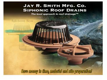
Save money in time, material and site preparation
Description:
Regularly Furnished: Duco Cast Iron Body with Combination Flashing Clamp and Air Baffle. ... Flashing is secured by a non-puncturing flashing clamp. Precast Deck ... – PowerPoint PPT presentation
Number of Views:211
Avg rating:3.0/5.0
Title: Save money in time, material and site preparation
1
Save money in time, material and site preparation!
2
Siphonic Roof Drains - The Level Approach to Roof
Drainage
Introduction/History and Brief Summary Listings/C
ertifications/Codes/Standards Myths and
Misconceptions Basic Principle of Siphonic Roof
Drainage Benefits of Siphonic Roof Drainage
Siphonic Roof Drain Design Siphonic
Roof Drain Models Installation Engineering
Resources Applications Case Studies
Summary
3
History of the Technology
- The basic technology was invented by Mr. Olavi
Ebeling, a Finnish engineer and inventor. - Olavi patented his first siphonic roof drain in
1968. - His aim was to reduce the cost of roof drainage
systems, then required to be installed in copper
tube and fittings (expensive). - The first major installation was at a turbine
factory in Sweden in 1972. - Spread rapidly from Scandinavia to the UK and
then to Europe in the 1980s but not in the
United States. Several spin-off companies
appeared. - European Manufacturers sold Siphonic as a
complete system Design, Drains and Piping. Not
accepted in the United States. - First application in the U.S in 1999 at the
Boston Convention and Exhibition Center, South
Boston, MA. (Designed by John Rattenbury
Engineer in Boston using European Drains).
4
History of the Technology
- IKEA Home Furnishings imports technology into the
U.S. starting in 2002. (Several Designed by John
Rattenbury using European drains) - Siphonic Roof Drainage Fundamentals, PM
Engineer Magazine, 2001 (By John Rattenbury) - John Rattenbury partners with Jay R. Smith Mfg.
Company to manufacture a U.S. made Siphonic
Drains. - Jay R. Smith Mfg. Co. developed and started
marketing the first U.S. made siphonic roof
drain, 2006. - Code and Engineering Community Acceptance
continues in the United States.
5
Standards Codes
- ANSI/ASME A112.6.9 Siphonic Roof Drains
- Accredited in July 2005.
- Headed by John Rattenbury as Team Leader.
- ASPE Tech Standard 45 Siphonic Roof Drainage
- Passed Main Committee Ballot in 2006.
- Published/Issued 2007
- Headed by John Rattenbury as Work Group 45
Leader. - IPC UPC Both codes technical committees have
approved product reference for siphonic roof
drains within the next printing of their
respective codes. The IPC has approved references
to ASPE 45 and ASME A112.6.9. The UPC approved
the reference to ASPE 45. - State of Wisconsin Recently approved siphonic
roof drainage as an alternative engineered system
as part of the Plumbing Code. - State of Massachusetts Recently approved
siphonic roof drainage as an alternative
engineered system as part of the Plumbing Code
6
Siphonic Roof Drainage Systems In The United
States
Approvals for Current Projects Boston Museum of
Fine Arts, MA General Motors, Toledo, OH JFK
Airport Warehouse, NYC Bronx Terminal Market,
NY IKEA Home Furnishings, OH Salmon Bay Offices,
Seattle, WA TCP/Disney, Pasadena, CA Yale
University, New Haven, CT Santa Ana, CA Cherokee
Central Schools, Asheville, NC Target, Atlanta, GA
Installations Boston Convention Center, Boston,
MA IKEA Home Furnishings, Paramus, NJ IKEA Home
Furnishings, New Haven, CT IKEA Home Furnishings,
Bloomington, MN IKEA Home Furnishings, Atlanta,
GA IKEA Home Furnishings, Canton, MI IKEA Home
Furnishings, Bolingbrook, IL IKEA Home
Furnishings, Brooklyn, NY IKEA Home Furnishings,
Stoughton, MA WV Regional Jail Authority,
Roanoke, VA Target, Richfield, MN Claude Moore
Education Center, VA Barneys New York, Dallas,
TX US Census Bureau, Suitland, MD General Motors,
Lansing, MI General Motors, Flint, MI General
Motors, Fort Wayne, IN Target, Houston, TX
More than 650 million square feet worldwide
Many thousands of buildings. Nearly 7 million
square feet in the U.S.
7
Myths Misconceptions
8
Myth Number 1
Myth Siphonic systems drain water off of the
roof faster than conventional drainage
piping. Reality Although higher operating
velocities are achieved, the drainage rate is a
function of pipe size. They can drain as quickly
or slowly as desired. Siphonic roof drainage is
very good for controlled flow storm water
management requirements.
9
Myth Number 2
Myth Siphonic systems must to be engineered by
the manufacturer or supplier of the pipe and
drains. Reality All siphonic systems
installed in the United States have been
engineered by an independent consulting engineer
(PE). Some companies advertise that
specialized design and installation is
required, but this has been demonstrated to be
untrue and unnecessary in the United States.
10
Myth Number 3
Myth Pipe and fittings are specialized and
available only from foreign proprietary
sources. Reality Pipe and fittings used for
siphonic roof drainage systems in the United
States are the same as those used for
conventional plumbing systems. There are no
special manufacturers, materials or installers
needed for siphonic roof drainage systems.
11
Myth Number 4
Myth There is standing water in the pipe and
on the roof at all times in order to maintain a
siphonic operation, even while not
raining. Reality When it is not raining, the
roof and piping are dry. When it rains, a layer
of water develops on the roof, but in the same
way as with conventional atmospheric systems.
There is no residual standing water.
12
Myth Number 5
Myth Water builds up on the roof until a
critical level is reached and then the drains
open up to siphon the water off. Reality
Water build-up on the roof is not any different
than conventional systems. Partly full to full
bore is a smooth transition. This property is a
tested parameter for siphonic drains (15 second
rule).
13
Myth Number 6
Myth There must be valves, utility
connections or mechanical controls to make the
siphon work. Reality There are no valves,
controls, regulators or moving parts of any kind.
The system consists only of drains and piping.
The system operates in and out of full bore
naturally in reaction to varying rainfall
intensity.
14
What is Siphonic Roof Drainage?
- First Conventional Systems (Atmospheric)
- Open outlets.
- Pitched horizontal piping. Gradient of the
pipe induces downhill flow to the point of
discharge. - Piping is about 1/2 to 2/3 full. Only 1/3rd full
in vertical pipes. - Capacity is limited by the size of the drain and
the depth of water around it during a rain event. - Atmospheric pressure throughout the system.
- The most common, but least efficient roof
drainage solution.
15
Open Flow
Gravity Flow Systems In an open channel flow
system, water travels along the inner wall of a
vertical pipe. Approximately 1/3 of the cross
section of the pipe is water and the remaining
2/3 is air.
Air
Water
In principle, the same quantity of water can be
drained with a smaller pipe at higher
debris-carrying velocities.
Water (full bore)
Full Bore Flow
16
Main Principles of Siphonic Roof Drains
3
17
What is Siphonic Roof Drainage?
- Siphonic Systems (Closed, Sub-Atmospheric)
- Closed Outlets. Drain has an air baffle.
- Piping primes and operates 100 full (i.e.
full-bore flow). - Horizontal piping is not pitched like
conventional systems. - Capacity is determined by the piping system and
the height of the roof above the point of
discharge. Makes full use of gravity. - When system primes, the piping depressurizes.
- Water is drawn through the outlets and piping
faster than gravity channel flow alone.
18
Main Principles of Siphonic Roof Drains
3
19
Main Principles of Siphonic Roof Drains
3
20
Additional Benefits of Siphonic Drainage
The Fish Tank Analogy Siphonic action can be
observed when we drain water from a tank. A pipe
or hose filled with water is used with one end
dipped into a receiving tank and the other end
and discharging at a lower level. Note that the
path taken by the tube does not induce flow, only
the difference in elevation.
21
Main Principles of Siphonic Roof Drains
Wavy flow (Pattern 1) as seen during rainfall
events far below the piping systems ability to
prime. Light showers will typically produce this
flow condition until rainfall intensity increases
to a point where branch pipes can fully prime.
3
22
Main Principles of Siphonic Roof Drains
The so-called pulsating flow (Pattern 2)
ordinarily happens at the junctions at the branch
pipes with the main collection piping. This is
due to the sudden decrease is pipe velocity as
the water transitions from the smaller diameter
branch pipes to the larger main collection pipe.
At this juncture, a hydraulic jump occurs as the
fluid transitions from super-critical to
sub-critical flow. At this stage, sudden
increases in velocities take place accompanied by
decreases in pressure. Eventually the peaks of
these hydraulic jumps come in contact with the
crown of the pipe and begin to propagate
downstream
3
23
Main Principles of Siphonic Roof Drains
and (if the dimensional rainfall intensity
continues) the plug flow pattern (Pattern 3)
becomes prominent. As the rainfall event
increases in intensity or the time of
concentration is approaching, the pipe becomes
more full of water and Less full of air.
3
24
Main Principles of Siphonic Roof Drains
The high flow velocity of the water captures and
emulsifies the remaining air and a frothy
bubble flow forms (Pattern 4).
3
25
Main Principles of Siphonic Roof Drains
This frothy flow condition becomes gradually
clearer until all of the remaining air is purged
out of the point of discharge and only water is
present. Although a smart percentage of air is
always induced by the siphonic drains, it is
quickly carried downstream and a full-bore
(Pattern 5) condition occurs.
3
26
Main Principles of Siphonic Roof Drains
It is rare that a rainfall event will occur at
the exact design intensity for any sustained
period. Therefore, a system wiIl typically
experience flow Pattern 3 to Pattern 5 during
heavy rainfall. During light rainfall events,
Pattern 1 and 2 may develop, but roof drainage is
still accomplished and with a more efficient
sized pipe system.
3
27
Main Principles of Siphonic Roof Drains
How Traditional Gravity Drainage Works As seen in
illustration 1, a traditional gravity drainage
system consists of a network of roof drains
connected by open outlet to a vertical downpipe.
The pitch in the piping allows rainwater to flow
to a discharge point. This configuration
necessitates relatively large diameter stacks
which connect into an even larger underground
drainage network.
3
28
Main Principles of Siphonic Roof Drains
The pipe materials and fittings used with
siphonic roof drains are the same as those
required for traditional drainage systems. With a
flat, level design, long horizontal runs above
overhead ceilings are possible, as shown in
illustration 4. This reduces or even eliminates
the need for buried pipe and the associated costs
with trenching, bedding, and backfilling within
the buildings footprint. Siphonic systems are
designed to operate under sub-atmospheric
pressure when primed full. The horizontal piping
in the system can have higher velocities than the
terminal velocity that can be achieved in a
traditional vertical stack. Therefore, siphonic
roof drainage systems are more efficient in the
use of materials since smaller pipe diameters can
be specified to handle a wide range of rainfall
events.
3
29
Benefits of Siphonic Drainage
Why you should consider a siphonic roof drain
system
Reduced material costs - smaller pipe diameters
means less . Reduced underslab work and building
costs - level pipe installation overhead with
fewer vertical stacks. Pipe locations are highly
flexible (horizontal and stack). Higher flow
velocity - driving head up to 100 times that of
traditional system. Reduced exterior excavation,
backfill and underground piping and
structures. Opportunity to economically enable
rainwater harvesting.
4
30
Siphonic Roof Drain Anatomy
1
31
Additional Benefits of Siphonic Drainage
LEED (Leadership in Energy and Environment Design)
Conserving Water Reducing Energy
Consumption Reducing the depletion of natural
resources and materials Creating a sustainable
site Use of innovative design Improving indoor
environmental quality
4
32
Additional Benefits of Siphonic Drainage
LEED (Leadership in Energy and Environment Design)
Reduced Site Disturbance Recycled
Content Innovative Design (Reduced
Material) Stormwater Management, Rate and
Quantity Water Use Reduction (If used with
Rainwater Harvesting)
4
33
Siphonic Roof Drain Models
Function For use in engineered siphonic roof
drainage systems in flat roof of any
construction. Internal air baffle creates
siphonic drainage action producing a more
efficient drainage than conventional roof drains.
Function For use in engineered siphonic roof
drainage systems for gutters, parapets, small
balconies, sills, cornices, marquees and other
small overhanging areas where drainage of
rainwater is required. Air baffle creates
siphonic drainage action producing a more
efficient drainage than conventional gutter
drains.
5
34
Installation
Fig. no. 1005, Low Profile Dome
Product design uses all existing installation
accessories. Standard installation procedures
apply.
7
35
TOP MOUNT DRAIN ELEVATOR
36
Siphonic Roof Drain Models
Product data is provided to the specifier for
outlet size selection and hydraulic calculations.
Sizing is a function of the roof runoff factor,
design rainfall intensity and the area draining
to the roof drain.
6
37
Building X
48,000 square foot, two-story building. Six roof
drains _at_ 8,000 sf per drain. Code 2006
International Plumbing Code. Rainfall Intensity
4.0 inches/hour Determine the number of drains
required and where they are to be located.
38
Drain C
Discharge
Drain B
Drain A
39
Building X
2006 IPC, Chapter 11
40
Drain C
Discharge
Drain B
Size pipe as you normally would for atmospheric
system and determine discharge pipe size. Then
use half that pipe size as your starting pipe
size and work your way back to each roof drain.
Drain A
41
PDHonline.org Siphonic Roof Drainage Course
Number M256 M268 Go to www.PDHonline.org Registe
r as a Member (at no cost) Look up Course M256
M268 Download the Course Materials (at no
cost) Study on Your Own Time Take the Open-Book
Quiz Receive a Certificate of Completion for 12
PDHs
42
SiphoniTec SIPHONIC ROOF SYSTEM Design Tool and
Training Be an industry leader on large,
flat-roof rainwater harvesting design using a
siphonic system and engineering software.
FEATURES Designed by an engineer for
engineers Easy web-based design Calculation
details and imbalance tabs MS Excel report
features GUI tree design Load and remove
multiple projects Add to existing library Save
project to a simple file
43
Analysis by computer software saves time and
assures accuracy.
44
Drain C
Discharge
Drain B
Drain A
45
(No Transcript)
46
The remaining effort is to manipulate the branch
piping lengths, diameters, flows to drains, etc.
to minimize the residual heads and imbalance of
the system.
47
An evenly balanced system within acceptable
tolerance. Rule of thumb is 10 of the overall
height or 3 feet, whichever value is less.
Computer software aids in this design effort.
48
Drain B
49
Analysis by computer software saves time and
assures accuracy.
50
An evenly balanced system within acceptable
tolerance. Rule of thumb is 10 of the overall
height or 3 feet, whichever value is less.
Computer software aids in this design effort.
51
John Rattenbury Phone (781)-383-0542 Jrattenbur
y_at_rainwatermanagement.com
52
SiphoniTec SIPHONIC ROOF SYSTEM Training Be an
industry leader on large, flat-roof rainwater
harvesting design using a siphonic system and
engineering software.
FEATURES Install the software Review
engineering and mathematical design basis
Review standards, design experiences and approval
issues Review features and contents of training
manual Hands-on system design For more
information on siphonic roof drainage systems
contact J.R. Smith Mfg Co. www.irsmith.com For
engineering assistance contact RMS
www.rainwatermanagement.com or call 540-375-6750
53
Applications
Siphonic systems are especially ideal for low
rise buildings with large footprints and flat
roofs such as
Airport Terminals Convention Centers
Aircraft Hangers Warehouses
Covered malls
Factories Train
Stations Office
Complexes
Retail
Distribution Centers
8
54
Case Studies
Boston Convention and Exhibition Center, South
Boston, MA
Traditional Gravity System
Siphonic Solution
11
55
Case Studies
IKEA Home Furnishings, Stoughton, MA
14
56
Case Studies
IKEA Home Furnishings, Bloomington, MN
Siphonic Piping Overhead in Merchandise Warehouse
Maximum Clear Height
16
57
Overflow System
Spout
Spout
58
Listings/Certifications
Note Hydraulic tests were performed at CRM
Laboratory, United Kingdom, under the supervision
of HR Wallingford, on a test rig conforming to
the ASME Standard A112.6.9-2005. IAPMO Listed
File 5138.
20
59
Siphonic Roof Drainage Benefits Summary
22
60
Summary
Its Been Done. It Works. It Saves Money.
23
61
Summary
After Many Hours of research. . .
23
62
Summary
After Many Hours of research. . . Many hours of
extensive testing. . .
23
63
Summary
After many hours of research. . . Many hours of
extensive testing. . . We finally developed
a Roof Drain that really SUCKS!!!
23
64
Any Questions
65
Thank You for Your Time
66
The End
Recommended
CrystalGraphics Presentations


