
Generation and Fracturing of Thick Shells - PowerPoint PPT Presentation
Title:
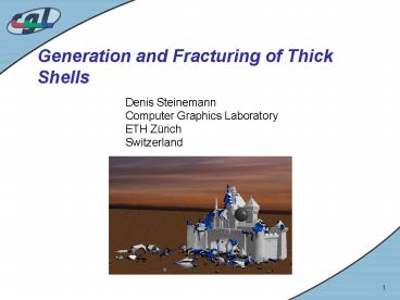
Generation and Fracturing of Thick Shells
Description:
Objects usually represented by surface meshes. ... Due to tessellation of shell, cracks often look jagged. Local re-meshing. Comparison ... – PowerPoint PPT presentation
Number of Views:47
Avg rating:3.0/5.0
Title: Generation and Fracturing of Thick Shells
1
Generation and Fracturing of Thick Shells
Denis Steinemann Computer Graphics Laboratory ETH
Zürich Switzerland
2
Motivation
- Objects usually represented by surface meshes.
For stable simulation of physics, need 3-d
volumetric representation. - Many objects in reality are hollow ? inefficient
to simulate over whole volume. 2.5-d Shell
(thick surface) sufficient. - Using 2.5-d representation, new fracture methods
become possible ? want to develop such methods
that work on shells.
3
Overview
- Previous Work
- Goals
- Implementation
- Shell Generation
- Fracturing and Deformation
- Rigid Bodies
- Results
- Software Demo
4
Previous Work
- Shell Generation
- Enveloping surfaces for mesh simplification
- Use only inner surface for shell
5
Previous Work
- Shell Animation
- FE-Methods
- FEM becomes slow for stiff materials, needs 3-D
volumes - Geometric approach
- stretching bending, but no thickness. Slow
OBrien
Müller
Grinspun
Wicke/Steinemann
6
Goals
- Shell Generation
- given a non-intersecting, non-manifold polygonal
surface mesh, construct thick surface - Requirements
- no (self-)intersections
- evenly distributed thickness
- Fracture
- simulate fracture and deformation of a shell
- real-time
- Should look physically realistic
7
Shell Generation
- Idea build a shell in small steps
- extrude vertices along opposite vertex normals
- if we detect a collision, move extruded vertices
back - I have developed two algorithms
- Single-Vertex Propagation
- Front Propagation
8
Single-Vertex Propagation
- Single-Vertex Propagation
- extrude one vertex at a time
- if a collision is detected, move vertex back and
try again, with half the step size. Try until no
collision between triangles is detected or step
size is too small - go on to next vertex vertex
- each vertex tries to make k moves without
collision
9
Single-Vertex Propagation
- Single-Vertex Propagation
- detects almost all intersections/overlaps
- maximizes and evenly distributes thickness
- slow because a lot of collision detection
10
Front Propagation
- Front Propagation
- extrude all vertices at once (the whole shell
front) - if a collision between triangles is detected,
move back all vertices part of a such a triangle - divide step size by 2 for those vertices
- move whole front again, k times
11
Front Propagation
- Front Propagation
- may not detect overlap
- ? sometimes smaller step size helps avoid this
- thickness may not be maximized or evenly
distributed, because no retries after vertex
moved back - faster than single-vertex propagation, because
less collision detection (no retries)
12
Stepsize Initialization
- How do we set the step sizes?
- Easy step size for vertex i
- Better precompute step size for each vertex
- Can avoid many collisions ? increase speed of
algorithm - Create line segment along opposite vertex normal,
length - Maximum vertex depth di distance to closest
intersection point divided by 2.
vi
vj
Step size
13
Fracturing
- Mass-Spring-Models
- compute dynamics and deformation
- Note fracturing is independent of force
computation ? possible to replace mass-spring by
FEM - fracture criteria is spring length if a spring
is too long, split one of its two vertices - One Layer of springs on original surface
- Fast
- Thickness info used for rendering
- Unstable ? Not suited for deformation and ductile
fracture
14
Fracturing
- Two layers of springs
- more stable ? can simulate ductile and brittle
fracture - Use surface and volume preservation forces in
addition to springs - can model thickness a thin shell is more easily
fractured than a thick one - Spring constants k proportional to thickness
Large k
small k
15
Fracturing
- 3 different types of fracture
- Fine-grained produces small pieces
- No constraints whenever a spring is too long,
split one of its vertices - Coarse-Grained produces larger pieces
- Constraint Keep some vertices from being split
Red vertices and springs cannot be split any more
16
Fracturing
- Large-Fragment Fracture fracture shell into few
but large pieces - Constraint Limit total number of splits
- Artificially extend cracks
- Due to tessellation of shell, cracks often look
jagged - Local re-meshing
- Comparison
17
Rigid Bodies
- Treat split-off shell fragments as rigid bodies
- Approximate fragment with object-oriented
bounding box to speed up simulation - Use Principal Component Analysis to compute OBB
- If a fragment is large, it must still be
breakable ? must be turned back to
mass-spring-model again
18
Results
- Shell Generation
- Computation time a few seconds for models with up
to 10000 vertices/triangles - Shell can be loaded from file, so this is not a
problem - Fracturing/Rigid Bodies
- See Software Demo
19
Future Work
- Shell Generation
- Manifold meshes
- Intersecting meshes
- Rigid Bodies
- No collision response between rigid body
fragments and mass-spring-model fragments yet - Do not approximate fragments by bounding boxes
for even more realistic behavior
?
20
Software Demo
- Have Fun!
Recommended
CrystalGraphics Presentations


