
Figure 5.1. Conversion from decimal to binary. - PowerPoint PPT Presentation
1 / 53
Title:
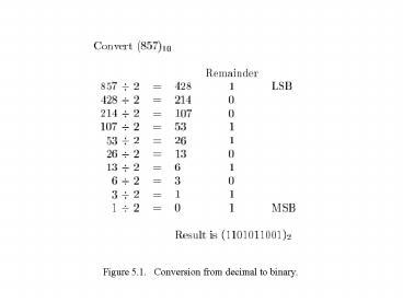
Figure 5.1. Conversion from decimal to binary.
Description:
Please see 'portrait orientation' PowerPoint file for Chapter 5. Figure 5.3. ... A ripple-carry adder based on expression 5.3. Figure 5.16. ... – PowerPoint PPT presentation
Number of Views:524
Avg rating:3.0/5.0
Title: Figure 5.1. Conversion from decimal to binary.
1
Figure 5.1. Conversion from decimal to binary.
2
Table 5.1. Numbers in different systems.
3
Please see portrait orientation PowerPoint file
for Chapter 5
Figure 5.2. Half-adder.
4
Figure 5.3. An example of addition.
5
Please see portrait orientation PowerPoint file
for Chapter 5
Figure 5.4. Full-adder.
6
s
c
s
i
i
HA
s
c
x
i
c
HA
c
i
1
y
i
(a) Block diagram
c
i
s
i
x
i
y
i
c
i
1
(b) Detailed diagram
Figure 5.5. A decomposed implementation of the
full-adder circuit.
7
x
y
x
y
x
y
1
1
0
0
n
1
n
1
c
1
c
c
c
c
FA
FA
FA
n
1
n
2
0
s
s
s
n
1
1
0
MSB position
LSB position
Figure 5.6. An n-bit ripple-carry adder.
8
Please see portrait orientation PowerPoint file
for Chapter 5
Figure 5.7. Circuit that multiplies an
eight-bit unsigned number by 3.
9
b
b
b
n
1
1
0
Magnitude
MSB
(a) Unsigned number
b
b
b
b
n
1
1
0
n
2
Magnitude
Sign
0 denotes
1 denotes
MSB
(b) Signed number
Figure 5.8. Formats for representation of
integers.
10
Table 5.2. Interpretation of four-bit signed
integers.
11
5
(
)
5
(
)
1 0 1 0
0 1 0 1
0 0 1 0
0 0 1 0
(
)
2
(
)
2
3
-
(
)
(
)
1 1 0 0
0 1 1 1
7
1 0 1 0
0 1 0 1
5
(
)
5
(
)
1 1 0 1
1 1 0 1
2
(
)
2
(
)
7
(
)
(
)
0 1 1 1
0 0 1 0
1
1
3
1
1
0 0 1 1
1 0 0 0
Figure 5.9. Examples of 1s complement addition.
12
5
(
)
(
)
1 0 1 1
0 1 0 1
5
0 0 1 0
0 0 1 0
2
(
)
2
(
)
(
)
7
(
)
3
1 1 0 1
0 1 1 1
5
(
)
(
)
1 0 1 1
0 1 0 1
5
1 1 1 0
1 1 1 0
2
(
)
2
(
)
7
(
)
1 0 0 1
0 0 1 1
1
1
3
(
)
ignore
ignore
Figure 5.10. Examples of 2s complement
addition.
13
0 1 0 1
5
(
)
0 1 0 1
0 0 1 0
2
(
)
1 1 1 0
3
(
)
1
0 0 1 1
ignore
1 0 1 1
1 0 1 1
(
)
5
(
)
0 0 1 0
1 1 1 0
2
1
1 0 0 1
(
)
7
ignore
5
(
)
0 1 0 1
0 1 0 1
1 1 1 0
0 0 1 0
2
(
)
7
(
)
0 1 1 1
1 0 1 1
1 0 1 1
5
(
)
(
)
1 1 1 0
0 0 1 0
2
1 1 0 1
(
)
3
Figure 5.11. Examples of 2s complement
subtraction.
14
0000
0001
1111
0010
1110
0
1
1
2
2
0011
1101
3
3
4
4
0100
1100
5
5
0101
1011
6
6
7
7
8
0110
1010
0111
1001
1000
Figure 5.12. Graphical interpretation of
four-bit 2s complement numbers.
15
y
y
y
0
1
n
1
Add
Sub
control
x
x
x
0
1
n
1
c
c
n
-bit adder
0
n
s
s
s
0
1
n
1
Figure 5.13. Adder/subtractor unit.
16
(
)
(
)
1 0 0 1
0 1 1 1
7
7
2
(
)
2
(
)
0 0 1 0
0 0 1 0
(
)
9
(
)
5
1 0 1 1
1 0 0 1
c
0
c
0
4
4
c
1
c
0
3
3
1 0 0 1
0 1 1 1
7
(
)
7
(
)
1 1 1 0
1 1 1 0
2
(
)
2
(
)
(
)
9
(
)
0 1 1 1
0 1 0 1
5
1
1
c
1
c
1
4
4
c
1
c
0
3
3
Figure 5.14. Examples of determination of
overflow.
17
x
y
x
y
1
1
0
0
g
p
g
p
1
1
0
0
c
1
c
c
0
2
Stage 1
Stage 0
s
s
1
0
Figure 5.15. A ripple-carry adder based on
expression 5.3.
18
x
y
x
y
1
1
0
0
x
y
0
0
g
p
g
p
1
1
0
0
c
0
c
2
c
1
s
s
1
0
Figure 5.16. The first two stages of a
carry-lookahead adder.
19
x
y
x
y
x
y
15
8
15
8
7
0
7
0
31
24
31
24
c
8
Block
Block
Block
c
c
c
c
32
24
16
0
3
1
0
s
s
s
31
24
15
8
7
0
Figure 5.17. A hierarchical carry-lookahead
adder with ripple-carry between
blocks.
20
x
y
x
y
x
y
15
8
15
8
7
0
7
0
31
24
31
24
Block
Block
Block
c
0
3
1
0
c
24
P
G
P
G
P
G
0
0
1
1
3
3
s
s
s
7
0
15
8
31
24
c
c
c
8
16
32
Second-level lookahead
Figure 5.18. A hierarchical carry-lookahead
adder.
21
x
y
x
y
1
1
0
0
g
p
g
p
1
1
0
0
c
0
c
2
c
1
s
s
1
0
Figure 5.19. An alternative design for a
carry-lookahead adder.
22
Figure 5.20. Schematic using an LPM
adder/subtractor module.
23
Figure 5.21. Simulation results for the LPM
adder.
24
LIBRARY ieee USE ieee.std_logic_1164.all
ENTITY fulladd IS PORT ( Cin, x, y IN
STD_LOGIC s, Cout OUT STD_LOGIC ) END
fulladd ARCHITECTURE LogicFunc OF fulladd
IS BEGIN s lt x XOR y XOR Cin Cout lt (x AND
y) OR (Cin AND x) OR (Cin AND y) END LogicFunc
Figure 5.22. VHDl code for the full-adder.
25
Please see portrait orientation PowerPoint file
for Chapter 5
Figure 5.23. VHDL code for a four-bit adder.
26
LIBRARY ieee USE ieee.std_logic_1164.all
PACKAGE fulladd_package IS COMPONENT
fulladd PORT ( Cin, x, y IN STD_LOGIC
s, Cout OUT STD_LOGIC ) END COMPONENT END
fulladd_package
Figure 5.24. Declaration of a package.
27
LIBRARY ieee USE ieee.std_logic_1164.all USE
work.fulladd_package.all ENTITY adder4
IS PORT ( Cin IN STD_LOGIC x3, x2, x1,
x0 IN STD_LOGIC y3, y2, y1, y0 IN
STD_LOGIC s3, s2, s1, s0 OUT STD_LOGIC
Cout OUT STD_LOGIC ) END adder4
ARCHITECTURE Structure OF adder4 IS SIGNAL
c1, c2, c3 STD_LOGIC BEGIN stage0 fulladd
PORT MAP ( Cin, x0, y0, s0, c1 ) stage1
fulladd PORT MAP ( c1, x1, y1, s1, c2 )
stage2 fulladd PORT MAP ( c2, x2, y2, s2, c3
) stage3 fulladd PORT MAP ( Cin gt c3,
Cout gt Cout, x gt x3, y gt y3, s gt s3 ) END
Structure
Figure 5.25. A different way of specifying a
four-bit adder.
28
LIBRARY ieee USE ieee.std_logic_1164.all USE
work.fulladd_package.all ENTITY adder4
IS PORT ( Cin IN STD_LOGIC X, Y IN
STD_LOGIC_VECTOR(3 DOWNTO 0) S OUT
STD_LOGIC_VECTOR(3 DOWNTO 0) Cout OUT
STD_LOGIC ) END adder4 ARCHITECTURE
Structure OF adder4 IS SIGNAL C
STD_LOGIC_VECTOR(1 TO 3) BEGIN stage0 fulladd
PORT MAP ( Cin, X(0), Y(0), S(0), C(1) )
stage1 fulladd PORT MAP ( C(1), X(1), Y(1),
S(1), C(2) ) stage2 fulladd PORT MAP ( C(2),
X(2), Y(2), S(2), C(3) ) stage3 fulladd PORT
MAP ( C(3), X(3), Y(3), S(3), Cout ) END
Structure
Figure 5.26. A four-bit adder defined using
multibit signals.
29
LIBRARY ieee USE ieee.std_logic_1164.all USE
ieee.std_logic_signed.all ENTITY adder16
IS PORT ( X, Y IN STD_LOGIC_VECTOR(15 DOWNTO
0) S OUT STD_LOGIC_VECTOR(15 DOWNTO 0) )
END adder16 ARCHITECTURE Behavior OF adder16
IS BEGIN S lt X Y END Behavior
Figure 5.27. VHDL code for a 16-bit adder.
30
LIBRARY ieee USE ieee.std_logic_1164.all USE
ieee.std_logic_signed.all ENTITY adder16
IS PORT ( Cin IN STD_LOGIC X, Y IN
STD_LOGIC_VECTOR(15 DOWNTO 0) S OUT
STD_LOGIC_VECTOR(15 DOWNTO 0) Cout,
Overflow OUT STD_LOGIC ) END adder16
ARCHITECTURE Behavior OF adder16 IS
SIGNAL Sum STD_LOGIC_VECTOR(16 DOWNTO 0)
BEGIN Sum lt ('0' X) Y Cin S lt
Sum(15 DOWNTO 0) Cout lt Sum(16) Overflow
lt Sum(16) XOR X(15) XOR Y(15) XOR Sum(15) END
Behavior
Figure 5.28. The 16-bit adder from Figure 5.27
with carry and overflow signals.
31
LIBRARY ieee USE ieee.std_logic_1164.all USE
ieee.std_logic_arith.all ENTITY adder16
IS PORT ( Cin IN STD_LOGIC X, Y IN
SIGNED(15 DOWNTO 0) S OUT SIGNED(15
DOWNTO 0) Cout, Overflow OUT STD_LOGIC )
END adder16 ARCHITECTURE Behavior OF adder16
IS SIGNAL Sum SIGNED(16 DOWNTO 0)
BEGIN Sum lt ('0' X) Y Cin S lt
Sum(15 DOWNTO 0) Cout lt Sum(16) Overflow
lt Sum(16) XOR X(15) XOR Y(15) XOR Sum(15) END
Behavior
Figure 5.29. Use of the arithmetic package.
32
ENTITY adder16 IS PORT ( X, Y IN INTEGER RANGE
-32768 TO 32767 S OUT INTEGER RANGE
-32768 TO 32767 ) END adder16 ARCHITECTURE
Behavior OF adder16 IS BEGIN S lt X Y
END Behavior
Figure 5.30. The 16-bit adder from Figure 5.27
using INTEGER signals.
33
Please see portrait orientation PowerPoint file
for Chapter 5
Figure 5.31. Multiplication of unsigned
numbers.
34
Please see portrait orientation PowerPoint file
for Chapter 5
Figure 5.32. A 4 x 4 multiplier circuit.
35
Please see portrait orientation PowerPoint file
for Chapter 5
Figure 5.33. Multiplication of signal numbers.
36
Figure 5.34. IEEE Standard floating-point
formats.
37
Table 5.3. Binary-coded decimal digits.
38
Please see portrait orientation PowerPoint file
for Chapter 5
Figure 5.35. Addition of BCD digits.
39
Please see portrait orientation PowerPoint file
for Chapter 5
Figure 5.36. Block diagram for a one-digit BCD
adder.
40
LIBRARY ieee USE ieee.std_logic_1164.all USE
ieee.std_logic_unsigned.all ENTITY BCD
IS PORT ( X, Y IN STD_LOGIC_VECTOR(3 DOWNTO
0) S OUT STD_LOGIC_VECTOR(4 DOWNTO 0) )
END BCD ARCHITECTURE Behavior OF BCD
IS SIGNAL Z STD_LOGIC_VECTOR(4 DOWNTO 0)
SIGNAL Adjust STD_LOGIC BEGIN Z lt ('0'
X) Y Adjust lt '1' WHEN Z gt 9 ELSE '0' S
lt Z WHEN (Adjust '0') ELSE Z 6 END
Behavior
Figure 5.37. VHDL code for a one-digit BCD
adder.
41
Figure 5.38. Functional simulation of the VHDL
code in Figure 5.37.
42
Figure 5.39. Circuit for a one-digit BCD adder.
43
Please see portrait orientation PowerPoint file
for Chapter 5
Table 5.4. The seven-bit ASCII code.
44
Convert (14959)10 Remainder Hex digit
14959 16 934 15 F LSB 934 16
58 6 6 58 16 3 10 A
3 16 0 3 3 MSB
Result is (3A6F)16
Figure 5.40. Conversion from decimal to
hexadecimal.
45
Figure 5.41. Conversion of fractions from
decimal to binary.
46
Please see portrait orientation PowerPoint file
for Chapter 5
Figure 5.42. Conversion of fixed point numbers
from decimal to binary.
47
Figure 5.43. A comparator circuit.
48
LIBRARY ieee USE ieee.std_logic_1164.all USE
work.fulladd_package.all ENTITY comparator
IS PORT ( X, Y IN STD_LOGIC_VECTOR(3 DOWNTO
0) V, N, Z OUT STD_LOGIC ) END comparator
ARCHITECTURE Structure OF comparator
IS SIGNAL S STD_LOGIC_VECTOR(3 DOWNTO 0)
SIGNAL C STD_LOGIC_VECTOR(1 TO 4)
BEGIN stage0 fulladd PORT MAP ( '1', X(0),
NOT Y(0), S(0), C(1) ) stage1 fulladd PORT
MAP ( C(1), X(1), NOT Y(1), S(1), C(2) )
stage2 fulladd PORT MAP ( C(2), X(2), NOT
Y(2), S(2), C(3) ) stage3 fulladd PORT MAP (
C(3), X(3), NOT Y(3), S(3), C(4) ) V lt C(4)
XOR C(3) N lt S(3) Z lt '1' WHEN S(3 DOWNTO
0) "0000" ELSE '0' END Structure
Figure 5.44. Structural VHDL code for the
comparator circuit.
49
LIBRARY ieee USE ieee.std_logic_1164.all
USE ieee.std_logic_signed.all ENTITY
comparator IS PORT ( X, Y IN
STD_LOGIC_VECTOR(3 DO V, N, Z OUT
STD_LOGIC ) END comparator
ARCHITECTURE Behavior OF comparator IS
SIGNAL S STD_LOGIC_VECTOR(4 DOWNTO 0)
BEGIN S lt ('0 X) - Y V lt S(4) XOR
X(3) XOR Y(3) XOR S(3) N lt S(3) Z lt
'1 WHEN S(3 DOWNTO 0) 0 ELSE '0' END
Behavior
Figure 5.45. Behavioral VHDL code for the
comparator circuit.
50
Figure 5.46. Multiplier carry-save array.
51
Figure P5.1. Circuit for problem 5.11.
52
LIBRARY ieee USE ieee.std_logic_1164.all
ENTITY problem IS PORT ( Input IN
STD_LOGIC_VECTOR(3 DOWNTO 0) Output OUT
STD_LOGIC_VECTOR(3 DOWNTO 0) ) END problem
ARCHITECTURE LogicFunc OF problem
IS BEGIN WITH Input SELECT Output lt "0001"
WHEN "0101", "0010" WHEN "0110", "0011"
WHEN "0111", "0010" WHEN "1001", "0100"
WHEN "1010", "0110" WHEN "1011", "0011"
WHEN "1101", "0110" WHEN "1110", "1001"
WHEN "1111", "0000" WHEN OTHERS END
LogicFunc
Figure P5.2. The code for problem 5.17.
53
0
0
0
0
0
1
0
1
0
2
0
2
1
0
0
1
1
1
0
2
1
2
1
0
2
0
0
2
2
1
1
0
2
2
1
1
Figure P5.3. Ternary half-adder.
Recommended
CrystalGraphics Presentations


