
Semiconductor diode - PowerPoint PPT Presentation
1 / 21
Title:
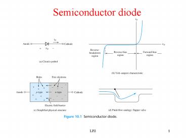
Semiconductor diode
Description:
ripple voltage, Vr and. Vr Q/C (L22) Eliminating Q from (L21) ... Capacitor size is half that of the half-wave case for the same load current and ripple voltage ... – PowerPoint PPT presentation
Number of Views:3247
Avg rating:3.0/5.0
Title: Semiconductor diode
1
Semiconductor diode
2
First approximation of a semiconductor diode
(Ideal-Diode)
iD
iD
R10 ?
R10 ?
Vs 10V
Vs 10V
iD 1A
iD 0A
3
Second approximation of a semiconductor diode
Diode on
iD
vD
Diode off
Vf ? 0.7V
iD
iD
R10 ?
R10 ?
Vs 10V
Vs 10V
iD 0.93 A
iD 0A
4
Third approximation of a semiconductor diode
Diode on
iD
vD /iD Diode body (bulk) resistance Rf
vD
Diode off
Actual Characteristics
Vf ? 0.7V
iD
iD
R10 ?
R10 ?
Vs 10V
Vs 10V
iD 0.62 A (say Rf 5 ?)
iD 0A
5
How to Find Out the Exact Diode Operating
point?
6
Example of Diode Load Line
If R 200 ? , Vss 3V in the what is iD and vD?
Operating point
7
Answer to the Diode Load Line Problem
iD 9.5 mA, vD 1.1 V
8
Multiple Ideal-Diode Circuit Analysis
- Assume either a on (short) or off (open)state
for a diode - Determine the current direction in an on diode.
- Determine the voltage polarity of an off diode.
- If the assumption is correct, current flows from
anode to - cathode in all on diodes cathode voltage
should be positive - with respect to anode in all off diodes.
- In a n diode circuit 2n such combinations are
possible
9
Example on Diode Circuit
10
What are the currents in D1,D2,D3,D4?
Assume ideal diodes
11
Answer and Another Question
iD1 2 mA, iD2 0 mA, iD3 0 mA, iD4 5 mA
What should be the minimum value of the current
source in the previous figure 10.17(c) in order
to make D3 conduct?
12
Rectifier Circuits
- Rectifier circuits convert AC voltage to DC
voltage - The output DC voltage magnitude is controlled by
controlling the input - AC voltage
- Usually classified by two types Half-wave and
Full-wave - Has many applications such as battery charger,
power supply.
13
Half-Wave Rectifier Circuits
- During the positive half-cycle of the source the
diode conducts - During the negative half-cycle the source diode
blocks - Current through the diode looks similar to the
voltage across RL
14
A simple Battery charger-Example of a Rectifier
- Can be used to charge a car battery from the
alternator
15
Smoothening the Output Voltage of a Rectifier-Add
a Capacitor across Load
16
Design of Filter Capacitor
- Assume capacitor takes negligible time to charge
- Assuming constant load current , the charge lost
by the capacitor is - Q
? ILT (L21) - The charge lost in the capacitor is reflected in
the load voltage as - ripple voltage, Vr and
- Vr ?
Q/C (L22) - Eliminating Q from (L21) and (L22) one gets
- C ILT
/ Vr (L23) - where T 1/f (f frequency of the input
sinusoidal source)
17
Design of Filter Capacitor(Contd..)
- Load Voltage VL Vm- Vr /2 where Vm peak of
- the sinusoidal source
18
Full-wave rectifier
- Normally used with center-tap transformer
- Rectifies both the positive and negative half
cycle - Capacitor size is half that of the half-wave case
for the same load current and ripple voltage
Vin
Vin
Vout
19
Diode-bridge Full-wave rectifier
- Can be used without a transformer
- Rectifies both the positive and negative half
cycle - Capacitor size is half that of the half-wave case
for the same load current and ripple voltage
(why?)
Vin
Vout
Vin
Vout
20
Comparison of Rectifier Circuits
With 12 transformer turns ratio With Large
C Peak Inverse Voltage (also with Large C)
21
SPICE simulation of Full-wave Bridge Rectifier
Circuit
Recommended
CrystalGraphics Presentations


