
Heavyweight High Impact Shock Testing - PowerPoint PPT Presentation
1 / 71
Title: Heavyweight High Impact Shock Testing
1
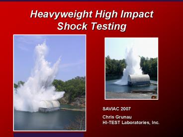
Heavyweight High Impact Shock Testing
SAVIAC 2007 Chris GrunauHI-TEST Laboratories,
Inc.
2
Outline
- 1. Brief History
- 2. Test Preparations Planning
- 3. Test Operations
- 4. Test Report
3
Section 1 Brief History of Shock Testing
- Prior to World War II
- During World War II
- Shock Test Machines
- Barge Testing
4
Brief History of Shock Testing
5
Brief History of Shock Testing
6
Brief History of Shock Testing
7
Brief History of Shock Testing
8
Brief History of Shock Testing
9
Floating Shock Platform (FSP)
FSP (16' x 31')
10
Section 2 Test Preparations
- Military Specification
- Test Procedure Preparation
- Test Fixture Design
- Procedure and Fixture Approval
- Contract
11
Government Documents
12
Government Documents
13
REFERENCES
- MIL-S-901D(NAVY) Military Specification, Shock
Tests, H.I. (High Impact) Shipboard Machinery,
Equipment, and Systems, Requirements for, dated
17 March 1989. - NRL Report No. 7396 Shipboard Shock and Navy
Devices for its Simulation, dated 14 July 1972. - NAVSEA Letter 9072 OPR 55X13, Ser. 55X1/164,
Shock Tests, H.I. (High-Impact) Shipboard
Machinery, Equipment, and Systems, Requirements
for, dated 30 October 1990. - DI-ENVR-80708 Shock Test Report, dated June
1986. - DI-ENVR-80709 High Impact Shock Test
Procedures, dated June 1986.
14
High Impact Shock Testing(MIL-S-901D)
- Lightweight Shock Machine (LWSM)
- Medium Weight Shock Machine (MWSM)
- Heavyweight Shock Testing Using the Floating
Shock Platforms (FSP, LFSP, and IFSP)
15
MIL-S-901D(NAVY) SCOPE
- Covers high impact shock testing requirements for
shipboard machinery, equipment, systems, and
structures, excluding submarine pressure hull
penetrators. - Verify ability of equipment to withstand shock
loadings - Intended to establish shock criteria to guide
contractor
16
ACQUISITION REQUIREMENTS
- Title, number, and date of MIL-S-901
- Other applicable specifications
- Shock Grade (A or B)
- Equipment Class (I, II, or III)
- Shock Test Type (A, B, or C)
- Mounting Location Aboard Ship
- Mounting Plane Aboard Ship
- Mounting Orientation Aboard Ship
- Method of Mounting Test Item
- Method of Simulating Shipboard Connections
- Mode(s) of Equipment Operation
- Shock Test Acceptance Criteria
- Acceptance Authority
17
SHOCK GRADE
- Grade A
- Essential to the safety and continued combat
capability of the ship. - Grade B
- Not essential to the safety and continued
combat capability of the ship but could
become a hazard to personnel or Grade A items.
18
GRADE A EQUIPMENT
- Ship Control and Propulsion
- Command and Control
- Navigation
- Communications
- Surface, Air, and Underwater Surveillance
- Countermeasures
- Lauching, Retrieving, Fueling, Defueling,
Rearming, and Handling of Aircraft and Small
Surface Craft - Essential Checkout and Maintenance of Aircraft
and Ordnance - Fire Control, Firing, or Launching, and Guidance
of Missiles and other Weapons
19
EQUIPMENT CLASS
- Class I
- Class II
- Class I/II
20
EQUIPMENT CLASS
- Class I
- Class II
- Class I/II
21
EQUIPMENT CLASS
- Class I
- Class II
- Class I/II
22
SHOCK TEST TYPE
- Type A
- Principal Unit (preferred test) - supported
directly by ship structure or installed in
piping systems or ducting systems - - Required in all cases unless size or weight
limitations are exceeded. - Type B
- Subsidiary Component. - Shock response of
Type A and C equipment are affected by Type B
equipment. - - Required when it is not possible to test a
principal unit due to size or weight
limitations. - Type C
- Subassembly. -Shock response of Type C
equipment is affected by Type A or B
equipment. -Shock response of Type A and B
equipment is not affected by Type C equipment. - - Required when it is not possible to test a
principal unit due to size or weight
limitations.
23
MOUNTING LOCATION
- Hull Mounted
- Deck Mounted
- Shell Mounted
- Wetted-Surface Mounted
- Note Shell and Wetted-Surface Mounted items
require a heavyweight shock test.
24
MOUNTING LOCATION
- Hull Mounted
- Deck Mounted
- Shell Mounted
- Wetted-Surface Mounted
- Note Shell and Wetted-Surface Mounted items
require a heavyweight shock test.
http//www.btinternet.com/warship/Today/bay.htm
25
MOUNTING PLANE ABOARD SHIP
- Base
- Front or Face
- Back
- Top
- Combination (base and back)
- Other
26
MOUNTING ORIENTATION ABOARD SHIP
- Restricted
- Unrestricted
- - Shot 4R is required for test in lieu of Shot 1
27
SIMULATION OF SHIPBOARD CONNECTIONS
- Piping, sway braces, drive shafts, control
linkages, or similar items - Restraining effects of connected items simulated
when test item derives a substantial degree of
support from the connected item. - Subsidiary Components and Subassemblies simulated
when not part of shock test.
28
OPERATION OF EQUIPMENT
- Grade A Items normal operation modes.
- Grade B Items operated if operating mode
increases potential of shock damage or a hazard. - No more than three most significant operating
modes represented during shock tests. - Operating performance during shock testing
monitored remotely to verify compliance with the
shock acceptance criteria.
Normal Mode
Standby Mode
Battleshort Mode
Recirculate
Pump
Bypass
29
OPERATION OF EQUIPMENT
- Remote Monitoring of Equipment
30
ACCEPTANCE CRITERIA
- Adrift Portions personnel and Grade A
equipment - Fire Hazards smoke, sparks, flame
- Minor Damagebroken, loose, or deformed parts
- Grade A Items Component must perform its
principal function - Grade B Items Component does not need to perform
principal function
31
RESOLUTION OF FAILURES
- Retest failed component if corrective design mod
is confined to subsidiary components or
subassemblies - Acceptance authority approval required
- Repeat qualifying shots (shots 1 and 4 or shots
4 and 4R)
32
- Test Fixture Design
- Minimum Rigid Adequately stiff and strong to
support equipment under test. - Simulates specific frequency or stiffness (Use of
DSF) - Class I Deck Mounted Items At Least 25 Hz
- Class II Deck Mounted Items 8-10 or 12-16 Hz
- Plastic Yielding/Cracking of Fixtures
- Hold-down bolts MIL-S-1222
33
- Test Fixture Design
34
- Test Fixture Design
35
- Test Fixture Design
Wetted-Surface Mounted Fixture
36
- Test Fixture Design
37
- Auxiliary Services
- Power Requirements
- 440 220, 120 VAC, 60 or 400 Hz, single or 3-phase
power, Maximum Amp, or DC service - Cooling Requirements
- Cooling Water specify flow and pressure
- Compressed air/Gases
- specify pressure, material, flow
- Fuel
- Lubricating/Hydraulic Oils
38
- Test Facility Considerations
- Statement of Work
- Consistent Nomenclature
- Equipment Class (Class I or Class II)
- Restricted or Unrestricted Orientations
- Mounting Location (Deck or Hull)
- Mounting Plane (Base, Back, Both)
- Drawings
- Installation Control Drawings (ICD)
- Weight, Dimensions, CG
39
- Test Facility Considerations
- Security Services
- Classified, Unclassified, COMSEC, Confidential,
Secret, Top Secret - Shipping to Test Facility
40
- Acceptance Authority Approval
Contractor-Furnished Equipment
Government-Furnished Equipment
NAVSEA 05P3(NSWCCD Philly) Code 669
NAVSEA 05P3(NSWCCD Philly) Code 669
Shipbuilding Supervisors(LW MW only)
Shipbuilder
Manufacturer
Government Entity
Shock Test Facility
Shock Test Facility
41
Section 3 Test Operations
- Test Fixture Fabrication
- Floating Shock Platforms
- Equipment Installation
- Instrumentation
- Test Operations
- Repairs
42
- Test Fixture Fabrication
- Performed by test facilities or in-house
43
Floating Shock Platform (FSP)
44
(No Transcript)
45
(No Transcript)
46
Intermediate Floating Shock Platform (IFSP)
IFSP (20' x 40')
FSP (16' x 31')
47
Intermediate Floating Shock Platform (IFSP)
48
Equipment Installation
FSP (16' x 30') with 14 Hz Deck Installed
FSP (16' x 22') with 25 Hz Deck Installed
49
Equipment Installation
FSP Test with Water System Installed
Dual decks for systems with multiple deck
frequency requirements
50
Deck Simulator Fixture
- DSF part of fixturing
- Vertical natural frequency
- -Mass of Payload
- -Pin Configuration
51
Deck Simulator Fixture
52
Deck Simulator Fixture
53
Equipment Installation
FSP (16' x 22') with 25 Hz Deck Installed
54
Equipment Installation
IFSP (20' x 40') Diesel Generator Set Installed
55
- Heavyweight Shock Test Limitations
- FSP
- 16' x 28'
- 60,000 - 120,000 lbs
- IFSP
- 20' x 40'
- 60,000 - 250,000 lbs
- LFSP
- 29'-9" x 50'
- 400,000 lbs
56
- Test Setup
- (Restricted Test Item on FSP)
Shot 2 (30)
Shot 3 (25)
Shot 4 (20)(Qualifying)
TestItem
Shot 1 (40)(Qualifying)
FSP
57
- Test Setup
- (Unrestricted Test Item on FSP)
Shot 2 (30)
Shot 3 (25)
Shot 4 (20)(Qualifying)
Shot 4R (20)(Qualifying)
TestItem
TestItem
FSP
FSP
Test Item Rotated 90?
58
- Charge Placement (FSP)
59
- Charge Placement (IFSP)
60
- Charge Placement (LFSP)
61
Note Shot direction for shot 1 is fore-and-aft.
Shot direction for shots 2, 3, and 4 is
athwartship. Represent primary mode of operation
during shots 1 and 4. Represent next likely mode
of operation during shot 3. Represent next
likely mode of operation during shot 2.
62
Heavyweight Shock Testing
IFSP (20' x 40') Testing of Diesel Generator Set
63
Video of Heavyweight Shock Test (Shot 4)
Single click to play, pause, or resume
64
Instrumentation
- Velocity Meters Dry/Wet
- Accelerometers
- Mechanical Deflection Gages
- Underwater Pressure Transducers
- Circuit/Current Monitoring
- Strain Gages
- High-Speed digital Cameras/Video
65
Instrumentation
LP Filter
Data Acquisition Processor
Velocity Meter
Accelerometer
Signal Conditioner
PC
Signal Conditioner/Power Supply
Mechanical Deflection Gage
66
Innerbottom Velocity
67
DSF Acceleration
68
DSF Frequency
14.6 Hz
69
Section 4 Test Report
- Written Per DI-ENVR-80708, Shock Test Report,
dated June 1986. - Submitted to Approval Authority
70
Completion!
- Submit Report
- Manufacture Equipment
- Take a vacation
- Any Questions?
71
HI-TEST LABORATORIES, INC.
Chris.Grunau_at_hitestlabs.com 434-581-3204
Recommended
CrystalGraphics Presentations


