
Balanced crosssections and computeraided modeling - PowerPoint PPT Presentation
1 / 29
Title:
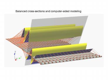
Balanced crosssections and computeraided modeling
Description:
A balanced cross-section (or interpretation) can be restored to the original ... In 2D cross-sections, mass does not move in or out of the section. ... – PowerPoint PPT presentation
Number of Views:208
Avg rating:3.0/5.0
Title: Balanced crosssections and computeraided modeling
1
Balanced cross-sections and computer-aided
modeling
2
Balanced cross-sections
- A balanced cross-section (or interpretation) can
be restored to the original (horizontal) form
without voids or gaps. - This means that the cross-section may be correct.
- A cross-section that cannot be restored must be
incorrect. - Assumptions
- Volume is neither created nor destroyed during
the process. - In 2D cross-sections, mass does not move in or
out of the section. - Usually done in depth, not time.
- Works best in sedimentary strata in upper crust
(low temperature and brittle deformation). - Most common in thrust terrains (poor seismic
images and less syndepositional growth) - Can be applied in extensional as well with care
- Does not work well in metamorphic or igneous
terrains - 3D balancing possible but usually requires
computational help (useful in salt or
strike-slip).
3
An example from the Zagros - Both are balanced
4
Classical balancing techniques
- Volume balancing.
- In 2D, reduces to balancing the area of a
formation. - Usually assume that bed thickness is constant
over area of the cross-section. - May need to include compaction effects.
- Line balancing
- If large-scale internal flow deformation does not
occur within the formation, then the bed length
will remain constant during deformation. - If a sedimentary bed is 2km long before
deformation, it should be 2km long after
deformation (but may be broken up). - Thick shales are usually the exception.
5
Line balancing
- Begin with pinning points where no deformation
has occurred. - Measure bed lengths between these two points.
- If the lengths do not match Houston, we have a
problem.
Which cross-section can be proven incorrect? (in
two ways)
6
Volume balancing example depth to detachment (in
a region with deformable layer/decollemont)
- Pick two pinning points.
- Estimate amount of shortening between pinning
points. - Measure amount of structural relief.
- Given the known shortening, calculate the
original thickness of the deformable layer.
Current length (L)
relief
Fold (area)
Amount of horizontal shortening (known)
Depth to detachment (fold area)/(shortening)
detachment
Original length (L0)
7
Difficulties
Great! We can check to see if a cross-section is
correct. But.how do we make a good one to start
with? the blank space problem With just
surface data and maybe some wells or bad seismic,
how do we start?
????
8
Make some assumptions! (e.g. Dahlstrom and Suppe)
- Thrust faults always step up.
- Thrust faults step up sharply and are not curved.
- Thrust faults in a given area step up at the same
angle for example, about 35-40 in basement
(e.g. granite) thrusts. - Folds can be drawn as kink folds.
- Dips steeper than the normal angle of thrusting
mean that several overlapping thrusts
(imbrications) exist.
9
- Use of kink methods
- Areas of constant dip separated by an axial
surface. - Bisect the angle between the bed dips.
- Use a scale of one-to-one
- Do rocks really do this?
- Sometimes.but it is an approximation also.
- In Suppe style, thrusts are assumed to have a set
cutoff angle. - Higher dips are the result of overlapping
thrusts.
From Katterhorn, 1994
10
Computer-aided
Ranges from simple (line balancing) to complex
(finite-element models). Conducted in
depth. Usually takes a lot of time to construct
3D models. Can be used for input for depth
migration, ray tracing, etc.
11
Compressional tectonics and seismic expression
From Chatelier, AAPG, Search and Discovery
12
Tectonic settings
Convergent boundaries Accretionary prism
(Barbados) Occur at subduction
zones Sediments scraped off descending
plate Fold and thrust belts Thin-skin
(Canadian Rockies) Most deformation occurs in
sediments above a regional decollemont May
involved a foreland basin Thick-skin
(Wyoming) Basement involved Higher angle
faults Inversion Re-activated older
faults Normal faults become compressional Transf
orm with compression (Los Angeles) Toe of
growth faults (Gulf of Mexico)
13
Seismic data
- Often poorly imaged, especially on land
- can be difficult and expensive acquisition due
to mountains with poor geometry. - large elevation changes and large statics
corrections - complicated velocity structure
- requires migration
- Use all other available data (surface, gravity,
etc) - Use knowledge of characteristic geometries and
lithologies - possible decollemonts (shales, salts)
- competent sections (carbonates)
- look for repeated sections
- anticlines and folds must have something
underneath - Constrain possible solutions with balanced
cross-sections and restorations - Think in 3D and be imaginative!
14
Accretionary prisms
thrusts
decollemont
- Nankai trough (subduction zone off southeast
Japan) - Sediments scraped off descending plate
- High fluid pressures
- Thrust faults
- Note decollemont
15
3D seismic (from Shipley) Amplitude variations
along decollemont possible variations in fluids
and fault strength?
16
Thin-skin thrusts
- Deformation occurs above a regional decollemont
- usually in sediments
- layers above decollemont may appear undisturbed
- ramp and flat geometry
- flat-lying thrust along weak layers (shales,
salt) - ramps up at defined angle in stronger layers
- often forms imbrications and duplexes
- Eventually, tectonic shortening involves basement
somewhere - Canadian Rockies are classic example
17
- A variety of structures
- usually hard to recognize on seismic
- useful for filling in blank spots to balance
sections
From Boyer and Elliott (1982)
18
Thick-skin
- Basement involved
- Higher-angle
19
Sort of a dumb animation
20
And now think in 3D
Sheep mountain, Wyoming - An anticline above a
basement thrust
21
Thrust faults and 3D
- Vary along strike
- Smoothly with gradual loss of slip
- Abruptly with tear faults
- Variations create structures in the layers above
22
Inversion
- Structures which have undergone a reversal of
regional stress with reactivation of faults are
referred to as inversion - Usually, extensional to compressional
- Occur in salt tectonics as well
- Change in correlation across faults
- Changes in formation thickness opposite to
expected (thicker at structural highs instead of
depocenters)
An inverted extensional fault - from Gibbs, AAPG
23
Balanced cross-sections
- Restorable sections
- No missing pieces
- Thrust faults follow set geometries
- Faults break at certain angles
- Controls dip of overlying layers
- Higher dips indicate imbrication
24
Sometimes the structures arent as neat
25
Software can help
- 3D restoration software
- Import from interpretation
- Convert to depth
- Restore along faults
26
(No Transcript)
27
Structural inversion in more complex structures
28
And looking at rocks can help
29
Somewhere below Santa Barbara- from Chatelier,
AAPG SD
Recommended
CrystalGraphics Presentations


