
Robot Dynamics: Equations and Algorithms - PowerPoint PPT Presentation
1 / 47
Title:
Robot Dynamics: Equations and Algorithms
Description:
Link i has inboard joint, Joint i ... on link i through its inboard joint ... Inboard joint. outboard joint. Link i-1. Assume previous is true for link i; ... – PowerPoint PPT presentation
Number of Views:511
Avg rating:3.0/5.0
Title: Robot Dynamics: Equations and Algorithms
1
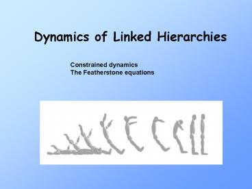
Dynamics of Linked Hierarchies
Constrained dynamics The Featherstone equations
2
Constrained dynamics
Apply force to one component, other components
repositioned, from near to far, to satisfy
distance constraints
F
3
Constrained Body Dynamics
- Chapter 4 in
- Mirtich
- Impulse-based Dynamic Simulation of Rigid Body
Systems - Ph.D. dissertation, Berkeley, 1996
4
Preliminaries
- Links numbered 0 to n
- Fixed base link 0 Outermost like link n
- Joints numbered 1 to n
- Link i has inboard joint, Joint i
- Each joint has 1 DoF
- Vector of joint positions q(q1,q2,qn)T
2
n
1
5
The Problem
- Given
- the positions q and velocities of the n
joints of a serial linkage, - the external forces acting on the linkage,
- and the forces and torques being applied by the
joint actuators - Find The resulting accelerations of the joints
6
First Determine equations that give absolute
motion of all links
Given the joint positions q, velocities and
accelerations Compute for each link the linear
and angular velocity and acceleration relative
to an inertial frame
7
Notation global variables
Linear velocity of link i
Linear acceleration of link i
Angular velocity of link i
Angular acceleration of link i
8
Joint variables
- joint position
joint velocity
Unit vector in direction of the axis of joint i
vector from origin of Fi-1 to origin of Fi
vector from axis of joint i to origin of Fi
9
Basic terms
- Fi body frame of link i
- Origin at center of mass
- Axes aligned with principle axes of inertia
Frames at center of mass
Fi
ri
di
Fi-1
Need to determine
- ui
Axis of articulation
State vector
10
From base outward
- Velocities and accelerations of link i are
completely determined by - the velocities and accelerations of link i-1
- and the motion of joint i
11
First determine velocities and accelerations
- From velocity and acceleration of previous link,
determine total (global) velocity and
acceleration of current link
Computed from base outward
To be computed
Motion of link i
Motion of link i-1
Motion of link i from local joint
12
Compute outward
- Angular velocity of link i
- angular velocity of link i-1 plus
- angular velocity induced by rotation at joint i
Linear velocity linear velocity of link i-1
plus linear velocity induced by rotation at
link -1 plus linear velocity from translation
at joint i
13
Compute outward
Angular acceleration propagation
Linear acceleration propagation
Rewritten, using
and
(from previous slide)
(relative velocity)
14
Compute outward
Angular acceleration propagation
Linear acceleration propagation
- Need
In terms of joint axis motion
15
Define wrel and vrel and their time derivatives
Joint acceleration vector
Joint velocity vector
Axis times parametric velocity
Axis times parametric acceleration
(unkown)
prismatic
revolute
16
Velocity propagation formulae
(revolute)
linear
angular
17
Time derivatives of vrel and wrel
(revolute)
Joint acceleration vector
Change in joint velocity vector
From joint acceleration vector
From change in joint velocity vector
From change in change in vector from joint to CoM
18
Derivation of
(revolute)
19
Acceleration propagation formulae
(revolute)
Previously derived
linear
angular
20
Spatial formulation of acceleration propagation
(revolute)
- But remember
- is an unknown
21
First step in forward dynamics
- Use known dynamic state
- Compute absolute linear and angular velocities
- Remember Acceleration propagation equations
involve unknown joint accelerations
But first need to introduce notation to
facilitate equation writing
Spatial Algebra
22
Spatial Algebra
- Spatial velocity
Spatial acceleration
23
Spatial Transform Matrix
r offset vector
R rotation
(cross product operator)
24
Spatial Algebra
Spatial transpose
- Spatial force
Spatial joint axis
Spatial inner product
(used in later)
25
ComputeSerialLinkVelocities
(revolute)
- For i 1 to N do
R?rotation matrix from frame i-1 to i
r?radius vector from frame i-1 to frame i (in
frame i coordinates)
Specific to revolute joints
end
26
Spatial formulation of acceleration propagation
(revolute)
Previously
Want to put in form
Where
27
Spatial Coriolis force
(revolute)
These are the terms involving
28
Featherstone algorithm
- Spatial acceleration of link i
Spatial force exerted on link i through its
inboard joint
Spatial force exerted on link i through its
outboard joint
All expressed in frame i
Forces expressed as acting on center of mass of
link i
29
Serial linkage articulated motion
Spatial articulated inertia of link I
articulated means entire subchain is being
considered
Spatial articulated zero acceleration force of
link I (independent of joint accelerations)
force exerted by inboard joint on link i, if link
i is not to accelerate
Develop equations by induction
30
Base Case
Consider last link of linkage (link n)
Force/torque applied by inboard joint gravity
inertiaaccelerations of link
Newton-Euler equations of motion
31
Using spatial notation
Link n
Inboard joint
32
Inductive case
Assume previous is true for link i consider link
i-1
Link i-1
outboard joint
Inboard joint
33
Inductive case
The effect of joint I on link i-1 is equal and
opposite to its effect on link i
Substituting
34
Inductive case
Invoking induction on the definition of
35
Inductive case
Express ai in terms of ai-1 and rearrange
Need to eliminate from the right side of the
equation
36
Inductive case
Magnitude of torque exerted by revolute joint
actuator is Qi
A force f and a torque t applied to link i at the
inboard joint give rise to a spatial inboard
force (resolved in the body frame) of
u
d
f
t
Moment of force
Moment of force
37
Inductive case
previously
and
Premultiply both sides by
substitute Qi for sf , and solve
38
And substitute
39
And form I Z terms
To get into form
40
Ready to put into code
- Using
- Loop from inside out to compute velocities
previously developed (repeated on next slide) - Loop from inside out to initialize I, Z, and c
variables - Loop from outside in to propagate I, Z and c
updates - Loop from inside out to compute using I, Z,
c
41
ComputeSerialLinkVelocities
(revolute)
// This is code from an earlier slide loop
inside out to compute velocities
- For i 1 to N do
R?rotation matrix from frame i-1 to i
r?radius vector from frame i-1 to frame i (in
frame i coordinates)
Specific to revolute joints
end
42
InitSerialLinks
(revolute)
// loop from inside out to initialize Z, I, c
variables
- For i 1 to N do
end
43
SerialForwardDynamics
// new code with calls to 2 previous routines
Call compSerialLinkVelocities
Call initSerialLinks
// loop outside in to form I and Z for each linke
- For i n to 2 do
// loop inside out to compute link and joint
accelerations
For i 1 to n do
44
And thats all there is to it!
45
(No Transcript)
46
(No Transcript)
47
(No Transcript)
Recommended
CrystalGraphics Presentations


